Belt-driven conical-pulley transmission

a conical-pulley transmission and belt-driven technology, applied in the direction of gearing elements, belts/chains/gearings, portable lifting, etc., can solve the problems of high leakage losses, and achieve the effect of cost saving and simple mounting

Inactive Publication Date: 2005-09-01
SCHAEFFLER TECH AG & CO KG
View PDF9 Cites 10 Cited by
  • Summary
  • Abstract
  • Description
  • Claims
  • Application Information

AI Technical Summary

Benefits of technology

[0018] The invention is based upon the objective of refining a belt-driven conical-pulley transmission with a drive side and an output side conical disk pair, wherein a conical disk pair is arranged on a shaft and includes a fixed disk constructed in one or several pieces with the shaft, and a movable disk non-rotatably connected with and axially movable relative to the shaft. A support ring is axially fixedly attached on the shaft at a distance from a back side of the movable disk, and at least one pressure chamber is constructed axially between the support ring and the back side of the movable disk. The pressure chamber is supplied with a hydraulic pressure medium through one or more passages constructed in the shaft and opening into a peripheral surface of the shaft, and whose pressure for displacing the movable disk is changeable. The pressure chamber directly bordering on the shaft operates trouble free even at very high torques transmitted from the fixed disk, as well as guaranteeing oil supply from the shaft into the pressure cylinders of the conical disk pairs with simultaneous reduction of the stress upon the components, especially at very low temperatures.
[0020] It is advantageous to construct the movable disk with a collar ending in the end region in relation to the support ring. This way, a support length is attained over which the movable disk is braced on the shaft, so that tilting torques can be absorbed, which are applied to the movable disk as a consequence of forces acting from an endless torque-transmitting means of the belt-driven conical-pulley transmission.
[0028] A further advantageous realization of the invention provides that the shaft preferably has at least one radial passage bore hole provided with a countersink in the form of a bevel or curvature in the immediate vicinity of its tapering towards the seat of the support ring, and that simultaneously the support ring is provided with a circular groove at the place where the conical disk contacts. Alternatively, this groove can also be installed on an offset. In this way, a mitigation of the strength-side critical position occurs. Moreover, the costly and expensive reprocessing of the conical disk becomes unnecessary.
[0029] It is moreover advantageous, that a circular recess is present on the end of the collar of the conical disk, preferably in the form of a bevel or a crown. It is thereby significantly simpler to mount it, since the correlation of shaft bore hole and oil groove is unnecessary. This circular recess in the sealing support can already be provided during blank manufacture, which leads to considerable cost saving.

Problems solved by technology

In practice this means comparatively high leakage losses, especially if the pressure in pressure chamber 22 is high.

Method used


Image

  • Belt-driven conical-pulley transmission
  • Belt-driven conical-pulley transmission
  • Belt-driven conical-pulley transmission

Examples


Embodiment Construction

[0047] The same reference numbers are used in FIG. 1 as in FIG. 5, so that the already explained details do not need to be explained once again.

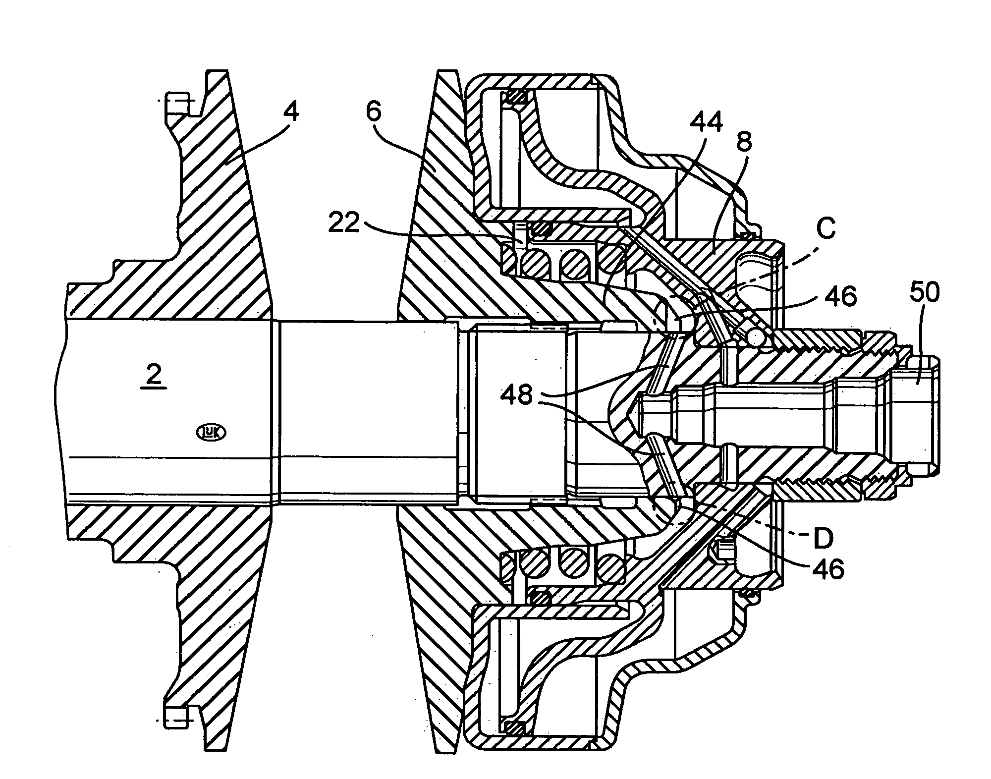
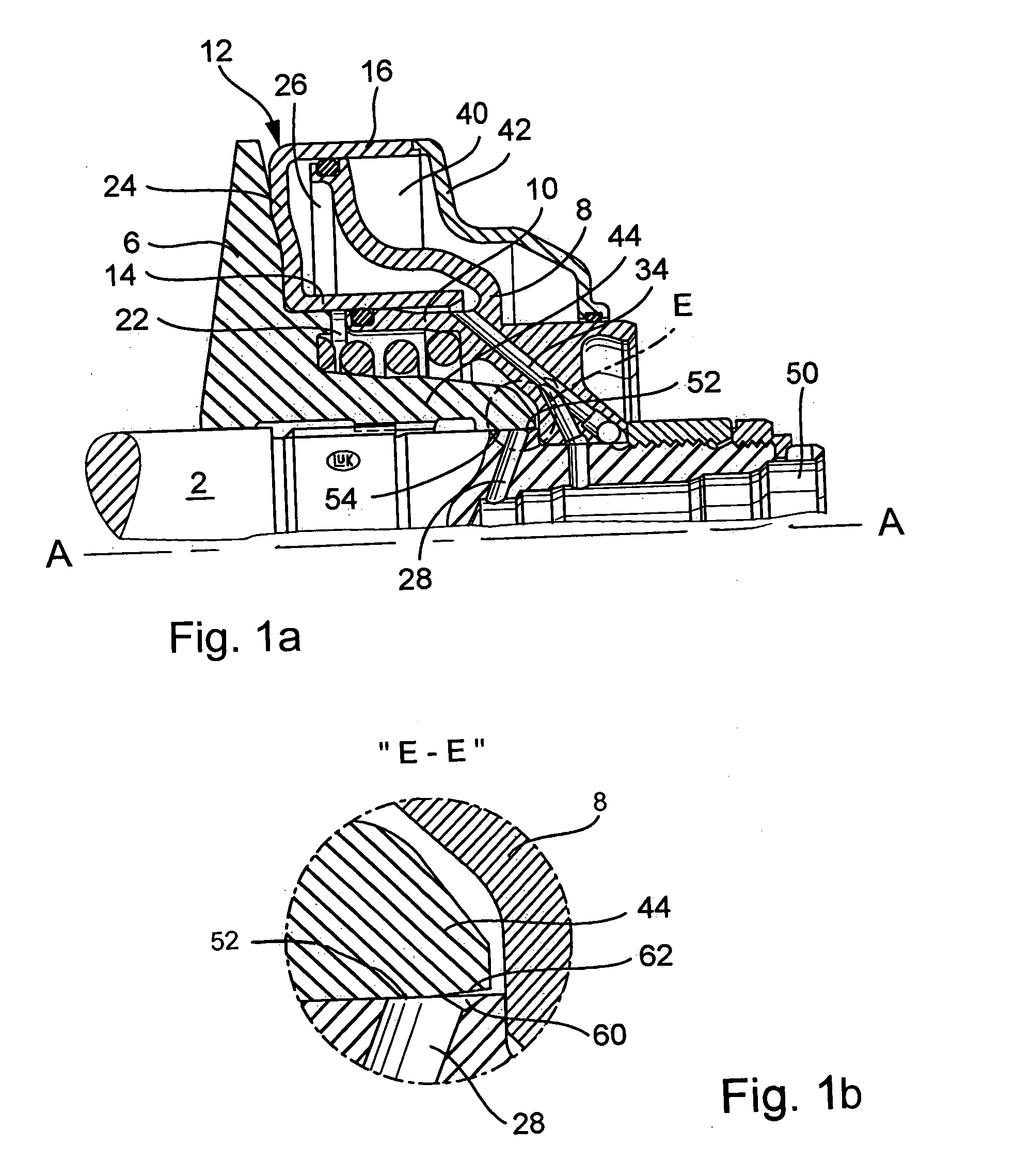
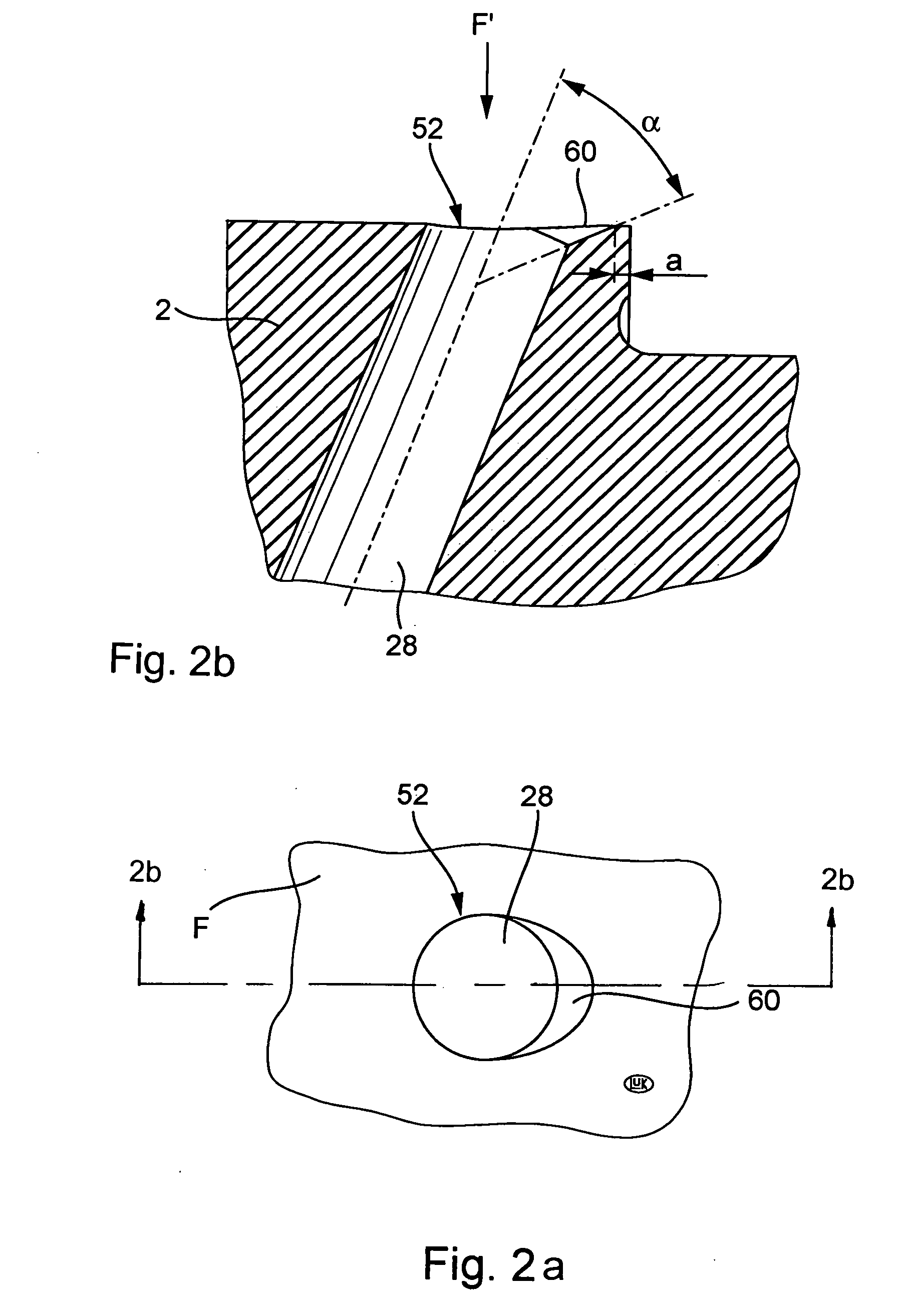
[0048] As opposed to the design in accordance with FIG. 5, the entire radial passage 28 of the shaft 2, which connects an axial passage 50 of the shaft 2 with the radially inner pressure chamber 22, is arranged in such a way that the aperture 52 of the entire radial passage 28 is passed over by the end region of the collar 44 of the movable disk 6, when the movable disk 6 is moved wholly to the right in accordance with FIG. 1.

[0049] Since the movable disk 6 and therewith also the collar 44 can be axially displaced in relation to shaft 2, there necessarily exists a play of up to about 50 μm between the inner surface of the movable disk 6 and the collar 44 guided on the outer surface of the shaft 2, for example the axially running inner surface 54 of the collar 44 and the outer surface of the shaft 2. A slight oval deformation, especially of...


PUM


Abstract

A transmission with a drive side and an output side conical disk pair. One conical disk pair includes a fixed disk carried by a shaft, a movable disk non-rotatably connected with and axially movable relative to the shaft, and a support ring axially attached to the shaft adjacent a back side of the movable disk. A pressure chamber between the support ring and the back side of the movable disk is supplied with hydraulic pressure medium through a passage in the shaft that opens to the surface of the shaft. An end region of the movable disk when moved along the shaft passes over the opening at a maximum spacing of the movable disk from the fixed disk, and a hydraulic medium connection exists between the passage and the pressure chamber through drainage slots between an inner surface of the movable disk and the peripheral surface of the shaft.

Description

CROSS-REFERENCE TO RELATED APPLICATION [0001] This is a continuation of International Application Serial No. PCT / DE2003 / 002373, with an international filing date of Jul. 15, 2003, and designating the United States, the entire contents of which is hereby incorporated by reference to the same extent as if fully rewritten.BACKGROUND OF THE INVENTION [0002] 1. Field of the Invention [0003] The invention concerns a belt-driven conical-pulley transmission with a drive side and an output side conical disk pair. [0004] 2. Description of the Related Art [0005] Belt-driven conical-pulley transmissions are recently increasingly being used in passenger cars. They not only make an increase in comfort possible, but also a decrease in fuel consumption. In order to expand the spectrum of use of belt-driven conical-pulley transmissions, intensive development efforts have been undertaken recently with respect to their capacity to transmit torque. [0006]FIG. 5 depicts the upper half of a half section ...

Claims


Application Information

Patent Timeline
Patent Type & Authority Applications(United States)
IPC IPC(8): F16H55/56F16H61/00F16H63/00F16H63/06
CPCF16H63/065F16H55/56
Inventor FAUST, HARTMUTMULLER, ERICSCHEUFELE, KLAUSGRUCA, WERNER
Owner SCHAEFFLER TECH AG & CO KG
Why Eureka
Try Eureka