Surgical retractor system

a surgical and retractor technology, applied in the field of surgical instruments, can solve the problems of increasing the price of each trocar, reducing the flexibility of the surgeon, and not being able to interchange different kinds or sizes of surgical instruments with permanent attachments

Inactive Publication Date: 2005-09-01
DEPUY SYNTHES PROD INC
View PDF61 Cites 39 Cited by
  • Summary
  • Abstract
  • Description
  • Claims
  • Application Information

AI Technical Summary

Benefits of technology

[0030] A handle may also be provided with the system which is configured to releasably secure the cannula to the handle. The handle may have a retractable slider pin for securing the cannula to the handle. The cannula may have a circumferential groove configured and adapt

Problems solved by technology

The permanent type attachment does not allow the surgeon to interchange different kinds or sizes of surgical instruments.
This reduced flexibility for the surgeon and increased prices for each trocar unit which must contain both a handle and permanently affixed cannula.
Overall inventory costs are thereby also increased.
Although the semi-permanent type couplings offer interchangeability of surgical instruments, they too have been problematic.
Using set screws or threaded coupling of th

Method used


Image

  • Surgical retractor system
  • Surgical retractor system
  • Surgical retractor system

Examples


Embodiment Construction

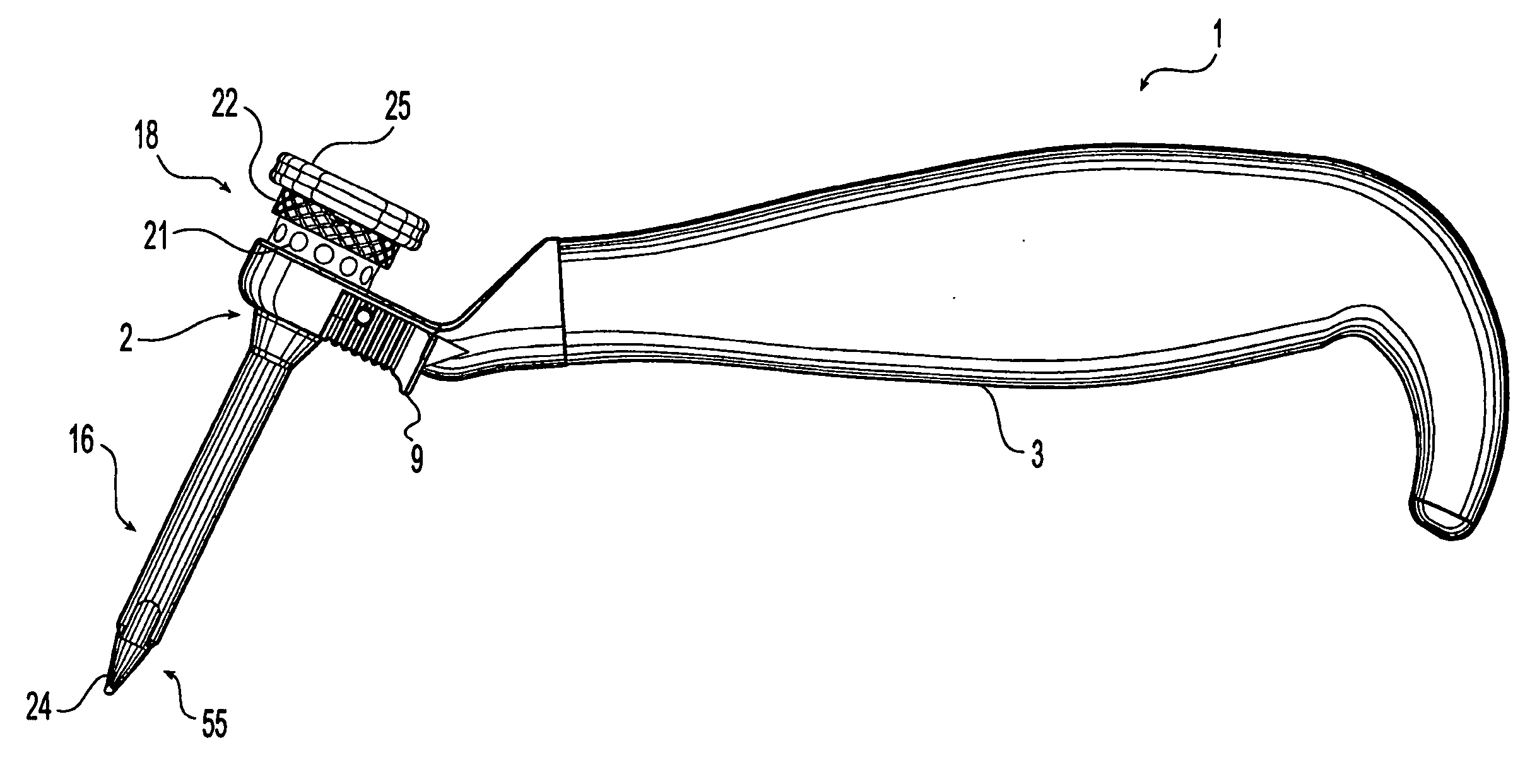
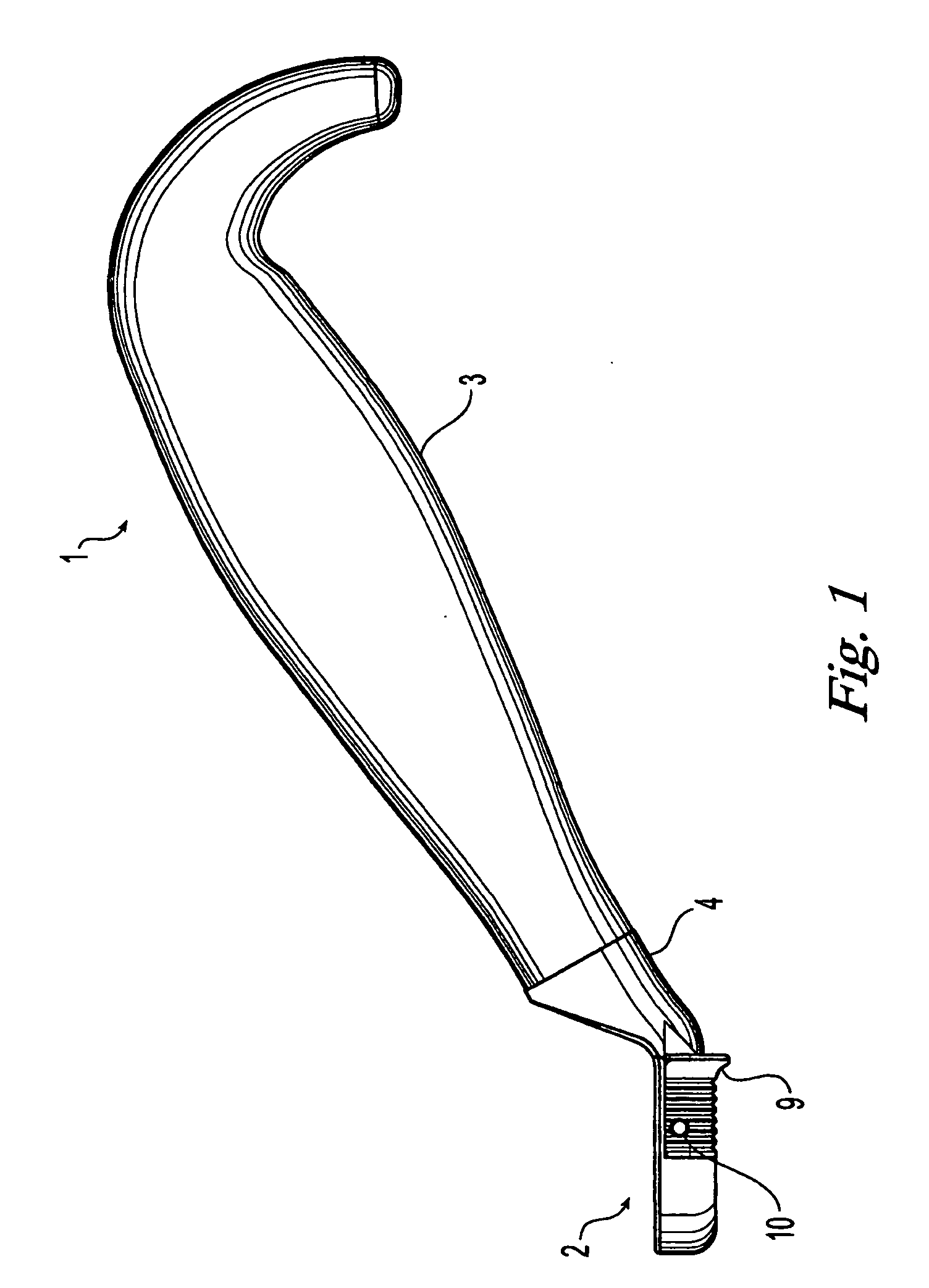
[0064] Referring to FIG. 1, the handle 1 is depicted in one embodiment as including a handle lock assembly 2 and a grasping portion 3. Handle lock assembly 2 may include a transition portion 4 connected to grasping portion 3 as shown; however, lock assembly 2 may be attached directly to grasping portion 3 with minimal or no transition depending on the shape and design of the handle 1 desired. It will further be readily apparent that the shape of the grasping portion 3 is a matter of ergonomic design choice and is not limited to the embodiment shown. Furthermore, grasping portion 3 may be formed of one or more pieces secured together in any manner commonly used in the art (e.g., welding, set screws, etc.) and may be either solid or hollow. It will also be appreciated that the size, shape, and position of the lock assembly 2 on the grasping portion 3 is a matter of design choice and is similarly not limited to the preferred embodiment shown.

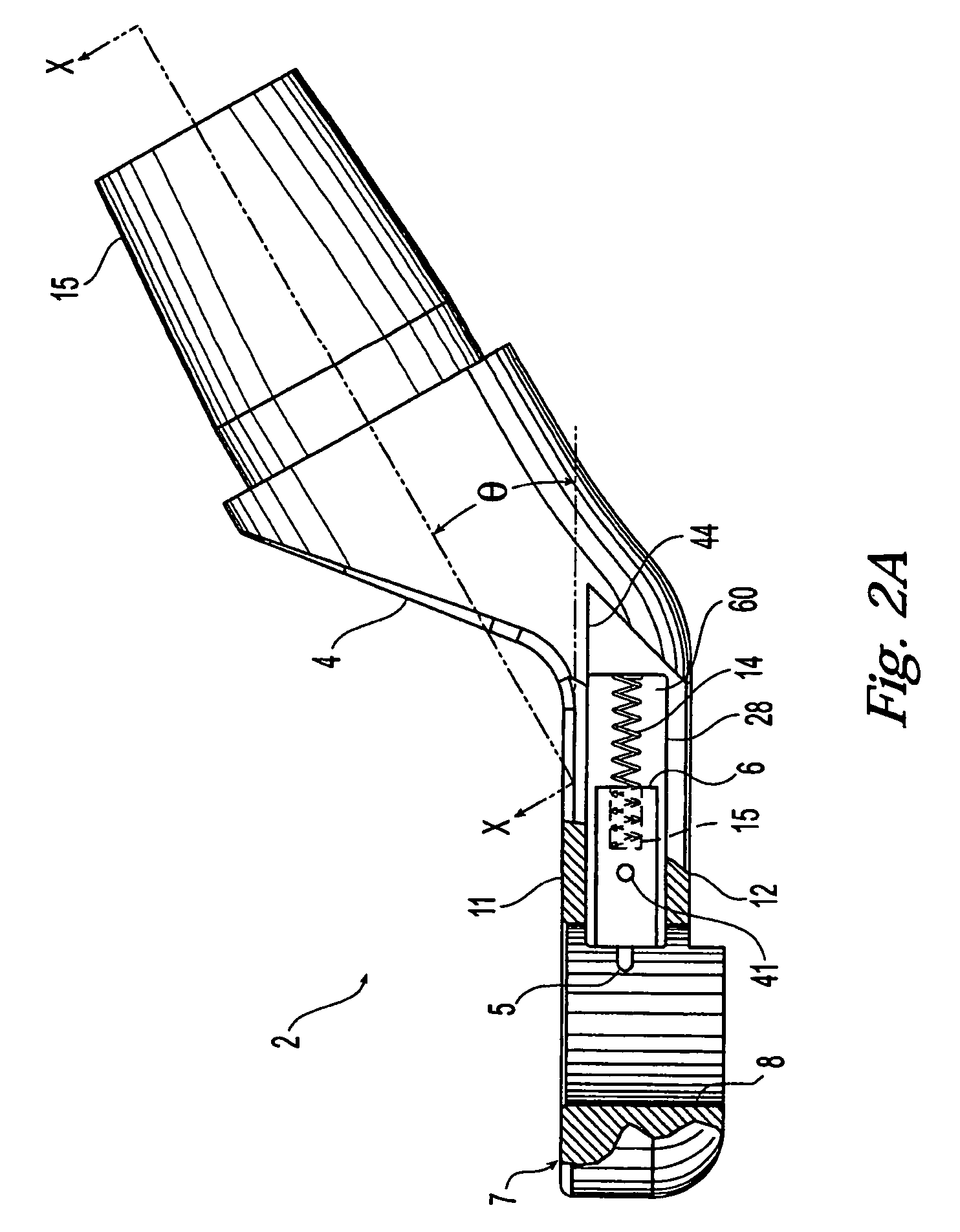
[0065]FIGS. 2A-2G depict the handle lock as...


PUM


Abstract

The present invention provides an improved surgical retractor system useful for holding tissue away from a surgical site during a medical or dental procedure. In one embodiment, the surgical retractor system is comprised of a tubular member, such as a cannula, and a retractor member. In an embodiment, the retractor member may be ring shaped. The retractor member preferably may have an opening therethrough for receiving the cannula. An engaging member associated with the retractor member may be provided for rotatably engaging the cannula. In one embodiment, the cannula may have external threads that are releaseably engaged with the engaging member and allows the degree or amount of tissue retraction to be adjusted. The cannula may be configured to be used with and secured to a handle to facilitate using the retractor system. A method of using the retractor system is also disclosed.

Description

CROSS-REFERENCE TO RELATED APPLICATIONS [0001] This is a continuation-in-part of U.S. patent application Ser. No. 09 / 742,254 filed Dec. 20, 2000, entitled “Universal Handle,” which is incorporated herein by reference.BACKGROUND OF THE INVENTION [0002] The present invention generally relates to surgical instruments used in surgical procedures, and more particularly to an improved handle that permits various instruments to be releaseably attached for quicker and easier interchange. [0003] The development of newer minimally invasive surgical techniques, such as laparoscopic surgery, have allowed surgeons to successfully perform numerous operative procedures in many instances which in the past required the need for large surgical incisions. In this newer procedure, one or several very small incisions are made in the patient through which various surgical instruments may be used to perform the required surgical procedure. Minimally invasive surgery offers benefits which include creating ...

Claims


Application Information

Patent Timeline
IPC IPC(8): A61BA61B1/00A61B1/32A61B17/00A61B17/02A61B17/17A61B17/34
CPCA61B1/32A61B2017/3492A61B17/0218A61B17/0281A61B17/17A61B17/24A61B17/34A61B17/3417A61B17/3421A61B2017/00265A61B2017/0042A61B2017/0046A61B2017/00477A61B2017/348A61B2017/3482A61B2017/349A61B17/02
Inventor HAMEL, ROSS J.VELIKARIS, JAMESKERR, SEAN
Owner DEPUY SYNTHES PROD INC
Why Eureka
Try Eureka