Wound drainage suction relief

Inactive Publication Date: 2005-09-01
HAEMONETICS
View PDF13 Cites 66 Cited by
  • Summary
  • Abstract
  • Description
  • Claims
  • Application Information

AI Technical Summary

Benefits of technology

[0014] In the above-described embodiments of the invention, fluid aspirated from the wound may be di

Problems solved by technology

A problem arising when using a drain catheter is that the tube perforations may become occluded, preventing further drainage of fluid.
If the occluded drain catheter is not cleared in a timely manner, fluid in the wound may accumulate, slowing the healing process and/or causing infection, as described above.
Additionally, an operator of the drain catheter may

Method used


Image

  • Wound drainage suction relief
  • Wound drainage suction relief
  • Wound drainage suction relief

Examples


Embodiment Construction

[0020] In illustrative embodiments, a wound drainage system that includes a drain catheter and a controller for aspirating fluids from a wound is presented. The system allows for intermittent relaxation of, thus helping to unclog and / or prevent obstruction of the drain catheter. Details are discussed below.

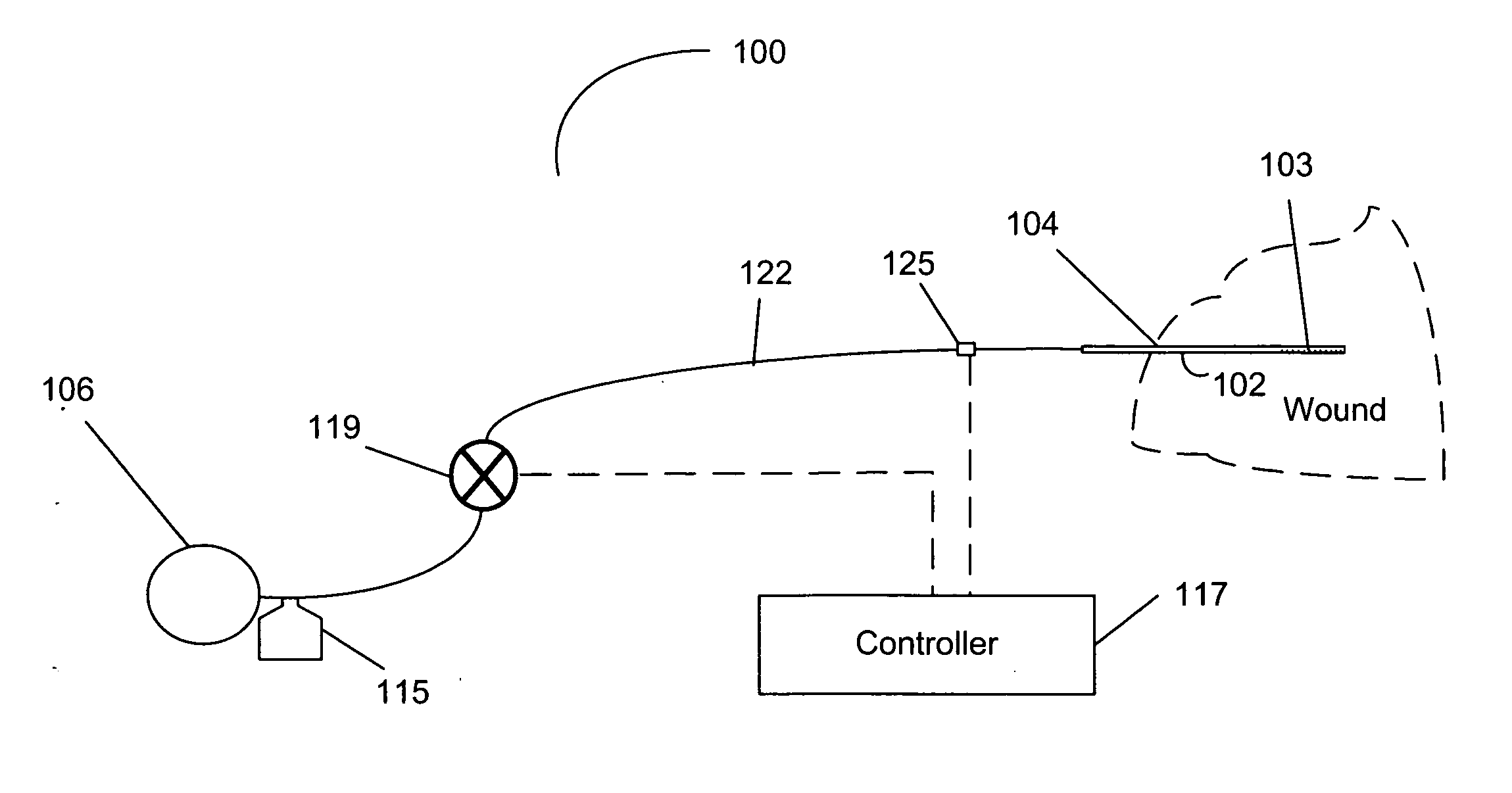
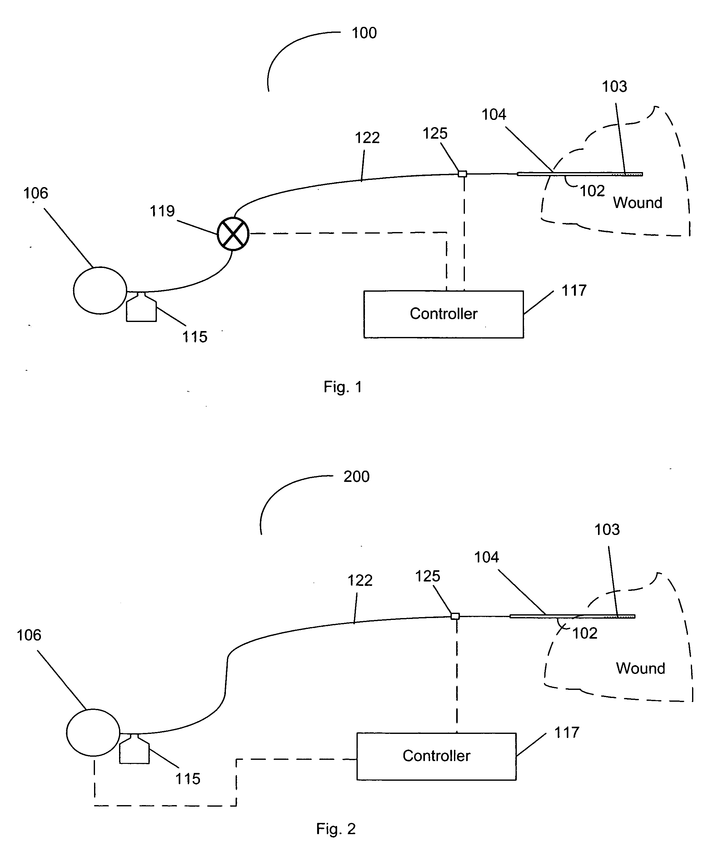
[0021]FIG. 1 is a illustration of a wound drainage system 100, in accordance with one embodiment of the invention. The system 100 includes a drain catheter 102 that generally includes a tubular body 104 defining at least one lumen through which fluid may pass. At a first end of the tubular body 104 are one or more perforations 103. Fluid from the wound, which may be, without limitation, a surgical site, is allowed to enter the tubular body 104 through the perforations 103, and can be drawn away from the wound though at least one lumen of the tubular body 104. In various embodiments, the drain catheter 102 may also include additional lumen to allow for passage of other fluids or g...


PUM


Abstract

In accordance with one embodiment of the invention, there is provided a wound drainage system for draining fluid from a wound of a patient. The system includes a drain catheter. A suction means applies suction at the drain catheter such that fluid is drawn from the wound. While drawing fluid from the wound, a controller periodically increases and decreases the application of suction at the drain catheter. This allows the tissue surrounding the wound drain to relax, thus preventing obstruction of the drain catheter.

Description

TECHNICAL FIELD [0001] The present invention generally relates to a device for providing drainage of a wound and more particularly, to a device that periodically increases and decreases the application of suction at a drain catheter. BACKGROUND ART [0002] It is often desirable to drain fluids from a wound. Fluids that can accumulate in the wound and lead to various complications include blood, serum, pus, bile or other biological fluids. Removal of these fluids can promote proper healing and reduce the threat of infection, thus reducing the amount of time spent in the hospital. [0003] A drain catheter can be used to drain fluids from the wound. The drain catheter typically includes a plastic tube having one or more perforations at one end. The perforated end of the tube is placed adjacent the wound, while the other end of the tube may be connected to a source of suction, which is typically wall suction present in an operating room. The suction causes fluid to be aspirated from the w...

Claims


Application Information

Patent Timeline
IPC IPC(8): A61M1/00A61M1/36A61M27/00
CPCA61M1/0037A61M27/00A61M1/3693A61M1/3696A61M1/3698A61M1/75
Inventor DOLLIVER, PHILLIP B.BOBROFF, ALEC
Owner HAEMONETICS
Why Eureka
Try Eureka