System and method for positioning a patient for laser surgery

a laser and positioning system technology, applied in laser surgery, medical science, surgery, etc., can solve problems such as misconfiguration of the system, problem of maintaining eye optical alignment with the laser system, and alignment errors

Active Publication Date: 2005-09-01
TECHNOLAS PERFECT VISION +1
View PDF29 Cites 133 Cited by
  • Summary
  • Abstract
  • Description
  • Claims
  • Application Information

AI Technical Summary

Problems solved by technology

Interestingly, alignment errors may result from either a misconfiguration of the system, or from the patient's interaction with the system.
When the eye is allowed to move independently of the system, however, maintaining an optical alignment of the eye with the laser system can be problematic.
On the other hand, those systems wherein the eye of the patient is placed and held in direct contact with the laser system, maintaining optical alignment between the eye and the laser system, still poses problems.
Either way, there are alignment issues that need to be addressed.

Method used


Image

  • System and method for positioning a patient for laser surgery
  • System and method for positioning a patient for laser surgery
  • System and method for positioning a patient for laser surgery

Examples


Embodiment Construction

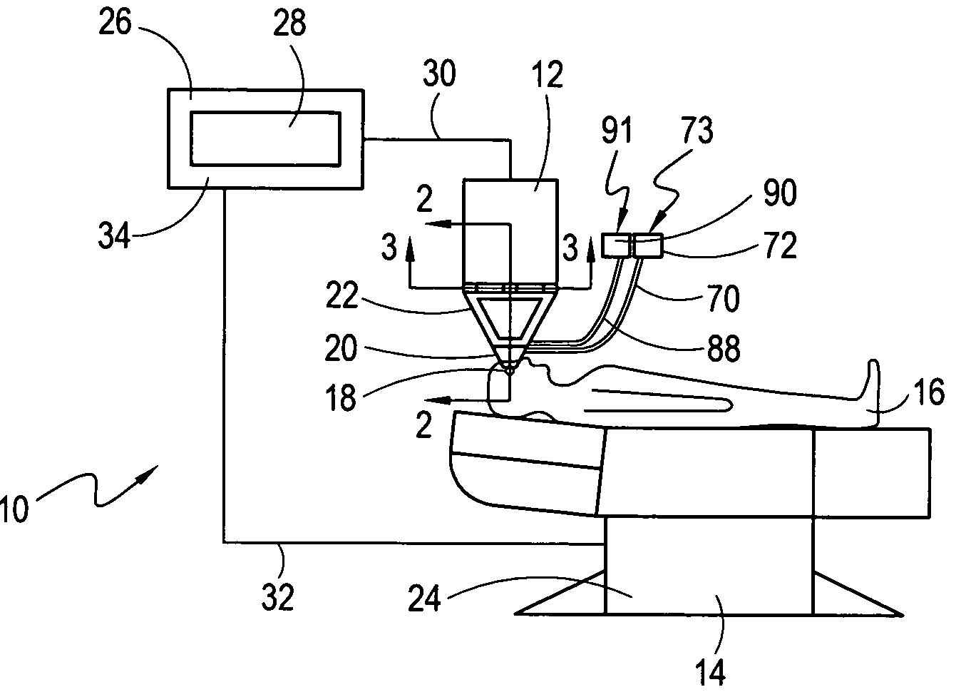
[0026] A system in accordance with the present invention is shown in FIG. 1 and is generally designated 10. As shown, the system 10 includes a stationary surgical laser unit 12 and a platform 14. More specifically, as disclosed herein, the platform 14 is used for supporting a patient 16, and positioning an eye 18 of the patient 16 relative to the surgical laser unit 12 during a laser surgery. Further, system 10 includes an eye stabilizing element 20 which is placed on the eye 18 and an alignment device 22 that is mounted or positioned on the laser unit 12 for engagement with the eye stabilizing element 20. Specifically, the alignment device 22 may be mounted on the surgical laser unit 12, or the device 22 may be integral to the surgical laser unit 12.

[0027] In the preferred embodiment of the present invention the platform 14 is a chair that includes a motorized control assembly 24 which can be selectively activated to move and reconfigure the chair 14. As shown in FIG. 1, the syste...


PUM


Abstract

A system for positioning the eye of a patient, relative to a stationary surgical laser unit, includes a chair for moving the patient. An eye stabilizing element is held against the eye, with a tapered receptacle extending outwardly therefrom. Also, an alignment device with a tapered tip is mounted on the surgical laser unit. In operation, the patient is moved to engage the receptacle of the eye stabilizing element with the tip of the alignment device, to thereby align the patient's eye with the surgical laser unit for laser surgery.

Description

FIELD OF THE INVENTION [0001] The present invention pertains generally to systems for performing laser refractive surgery. More particularly, the present invention pertains to systems for positioning the eye of a patient for laser refractive surgery. The present invention is particularly, but not exclusively, useful as a system and method for moving the eye of the patient to a predetermined location relative to a stationary surgical laser unit for performing laser refractive surgery. BACKGROUND OF THE INVENTION [0002] The current state of the art in refractive laser surgery involves ablating corneal tissue of the eye with an ultra-fast, ultra-short pulse duration laser beam. Indeed, it is well known that the ablation of selected corneal tissue can correct refractive errors of a patient's eye by permanently altering the structure of the cornea. A system for accomplishing this type of tissue ablation through laser surgery is disclosed in U.S. Pat. No. 6,610,051, entitled “A Device and...

Claims


Application Information

Patent Timeline
Patent Type & Authority Applications(United States)
IPC IPC(8): A61B17/30A61F9/007A61F9/009
CPCA61F9/009A61B2017/306
Inventor LOESEL, FRIEDERBAUMEISTER, KLAUSPAPE, ULRICH VONSAUTER, THOMAS
Owner TECHNOLAS PERFECT VISION
Why Eureka
Try Eureka