Method for synchronizing symbol timing

a symbol timing and symbol technology, applied in the field of digital signal processing and digital communications, can solve the problems of serious degrade system performance and short user data content of such a transmission, and achieve the effect of more accurate tan 2 results

Inactive Publication Date: 2005-09-01
PENTOMICS
View PDF12 Cites 26 Cited by
  • Summary
  • Abstract
  • Description
  • Claims
  • Application Information

AI Technical Summary

Benefits of technology

[0020] More specifically, the coarse angle computation is performed by retrieving a pre-computed Z0=1 / [X0] value from a reciprocal lookup table (e.g. memory device), where [X0] is a bit truncated approximation of X0. The Z0 value is multiplied by the Y0 component, resulting in a [Y0Z0] value. The coarse approximation angle φ1 is retrieved from a second lookup table that stores pre-computed arctan values of [Y0Z0]. Next, the input complex signal is multiplied by the [Y0Z0] value. This multiplication effectively rotates the input complex number by the coarse angle φ1 back toward the X-axis of the complex plane, resulting in an intermediate complex number having an X1 component and a Y1 component. Next the reciprocal lookup table is re-used to determine an approximation of Z1=1 / [X1]. Then the tangent of the fine angle φ2 is determined based on [Z1Y1], assuming that tan φ2 can be substantially approximated as [Z1Y1]. In embodiments, the Newton Raphson method is implemented to get a more accurate tan φ2 result. Finally, based on the smallness of tan φ2, the trigonometric function value tan φ2 is used as an approximation to φ2, hence requiring no arctan table.

Problems solved by technology

When there is a mismatch, then an undesirable rotation of the symbol constellation will occur at the receiver, which will seriously degrade system performance.
However, the user data content of such a transmission is usually very short.

Method used


Image

  • Method for synchronizing symbol timing
  • Method for synchronizing symbol timing
  • Method for synchronizing symbol timing

Examples


Embodiment Construction

[0107]

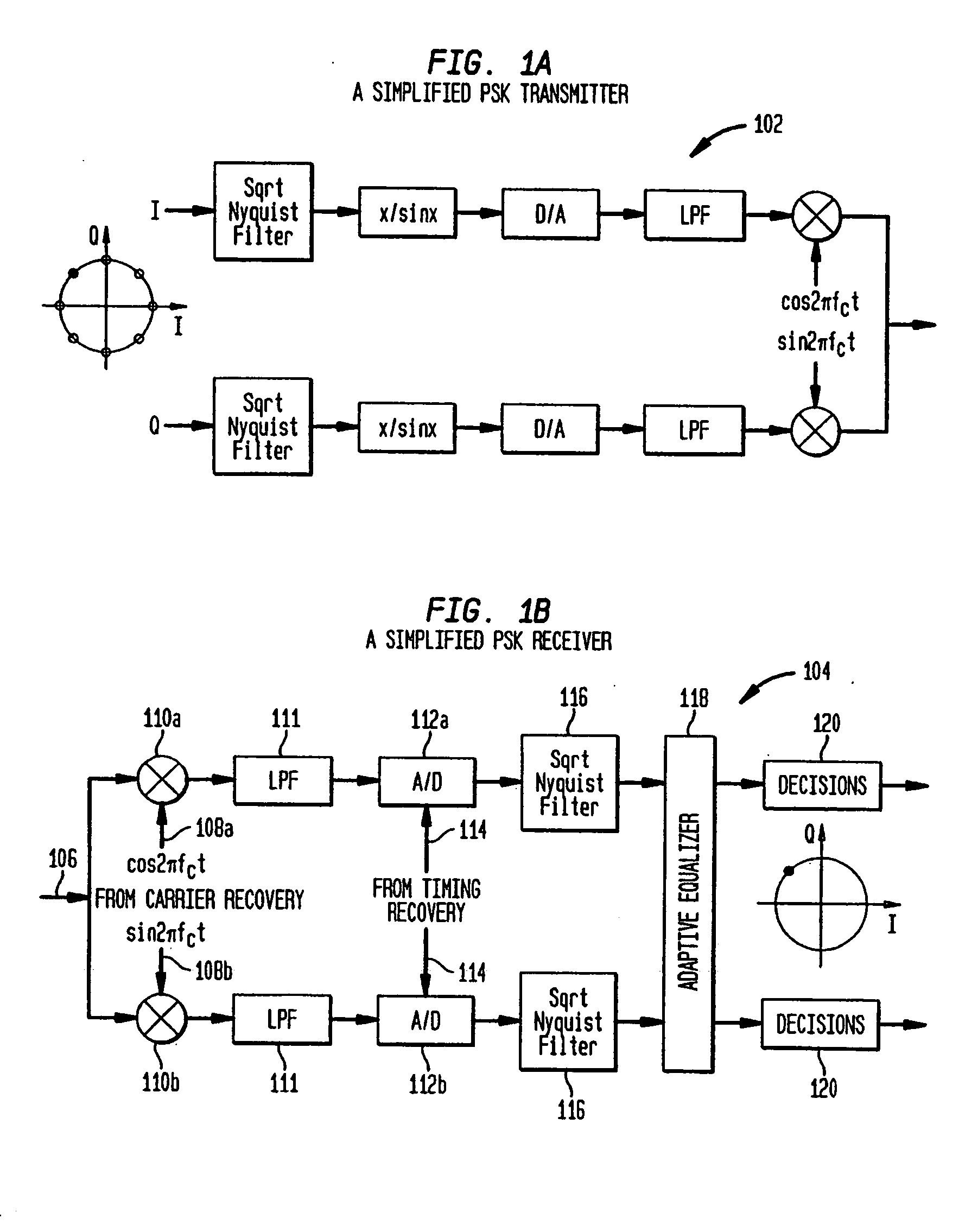
Table of Contents1.Introduction1.1Exemplary Modulation Schemes and Synchronization Issues1.2Overview2.Interpolation Using a Trigonometric Polynomial2.1Interpolation Using an Algebraic Polynomial2.2The Trigonometric Polynomial Method2.3Performance Comparisons2.4Efficient Implementation Structures2.4.1Using a Lookup Table2.4.2Using an Angle Rotation Processor2.5Delays in the Computation2.6Simplifications of the Preliminary Structures2.6.1The Simplified Structure for N = 42.6.2The Simplified Structure for N = 82.6.3Performance Comparisons with Other Structures2.7Trigonometric Interpolator Application2.8Trigonometric Interpolator Summary3.Interpolation Filters with Arbitrary Frequency Response3.1Formulating the Trigonometric Interpolator as an InterpolationFilter3.2Analysis of the Frequency Response3.3Implementing the Modified Algorithm3.4Conditions for Zero ISI3.5Optimization Algorithm3.6Conclusion4.Design of Optimal Resamplers4.1Motivation4.2Resampler Optimizations4.3Implementat...


PUM


Abstract

A method of synchronizing symbol timing in a digital device includes the steps of receiving complex data samples of one or more symbols, correlating the data samples with a complex conjugate of a preamble data set, selecting between real and imaginary samples and generating a complex number based on the result. The method then determines an angle in a complex plane that represents symbol synchronization for the digital device. Disclosed embodiments include applications to communications devices, and to carrier recovery in such devices. In such embodiments the resultant angle may represent a carrier phase offset for the device.

Description

[0001] This application claims the benefit of U.S. Provisional Application No: 60 / 162,391, filed on Oct., 29, 1999, which is incorporated herein by reference. CROSS-REFERENCE TO OTHER APPLICATIONS [0002] The following applications of common assignee are related to the present application, have the same filing date as the present application, and are herein incorporated by reference in their entireties: [0003]“Apparatus and Method for Trigonometric Interpolation,”; and [0004] Apparatus and Method for Angle Rotation,”.[0005] This invention was made with Government support under grant no. MIP 9632698 awarded by the National Science Foundation. The U.S. Government has certain rights in this invention.BACKGROUND OF THE INVENTION [0006] 1. Field of the Invention [0007] The present invention is related to digital signal processing and digital communications. More specifically the present invention is related to interpolation, angle rotation, rectangular-to-polar conversion, and carrier and...

Claims


Application Information

Patent Timeline
Patent Type & Authority Applications(United States)
IPC IPC(8): G06F7/38G06F17/10H04L27/22
CPCH04L27/22H03H17/0027H03H17/028
Inventor FU, DENGWEIWILLSON, ALAN N. JR.
Owner PENTOMICS
Why Eureka
Try Eureka