
Method for breaching ice dams on the roof of a house

Inactive Publication Date: 2005-09-08
PETROFF CHRISTOPHER
View PDF15 Cites 8 Cited by
  • Summary
  • Abstract
  • Description
  • Claims
  • Application Information

AI Technical Summary

Benefits of technology

[0019] It is another object of the present invention to provide an apparatus that does not need to be reapplied over a reasonable period.
[0020] It is a further object of the present invention that it can be placed on the roof without mechanical attachment to the roof.
[0022] An even further object of the present invention is that the low cost configuration does not require an external power supply.
[0023] Even still another object of the present invention is that both the high and low cost embodiments are inexpensive enough that they can be a last minute purchase by a consumer after the ice dam has formed.

Problems solved by technology

The ice dam usually forms at the lower edge of the roof because the thermal contact between the heat emanating from the building and the roof is not as good there as the rest of the roof.
It is common knowledge that ice dams can cause damage to the building structure.
Water damage to the interior can then ensue.
Roofing barriers are expensive and often aren't included in new construction.
Zig-zag electric heating wires require going onto the roof to install, require connection to house current and are expensive to operate.
They require installation before ice is on the roof, and are considered unaesthetic by many.
Consequently they are not very widely used, even in geographic areas that are subject to frequent formation of ice dams.
Ice tenaciously binds to roofing shingles and is difficult to remove.
Because roofing shingles are not designed to withstand mechanical ice removal, permanent damage the roof often occurs.
In addition, the removal of the ice dam by mechanical means requires walking on the roof or using a ladder, both of which are dangerous when snow cover is present.
While this method can prove effective, it is time consuming and needs to be repeated if the conditions for favorable ice dam formation continue.
This is time consuming and messy.
A disadvantage of first group of methods is that they can't be implemented after the ice dam has formed.
Since ice dam formation is a sporadic event that might not occur annually, prophylactic preparation for ice dams is not common and home dwellers are often left without protection if an ice dam forms.

Method used


Image

  • Method for breaching ice dams on the roof of a house
  • Method for breaching ice dams on the roof of a house
  • Method for breaching ice dams on the roof of a house

Examples


Embodiment Construction

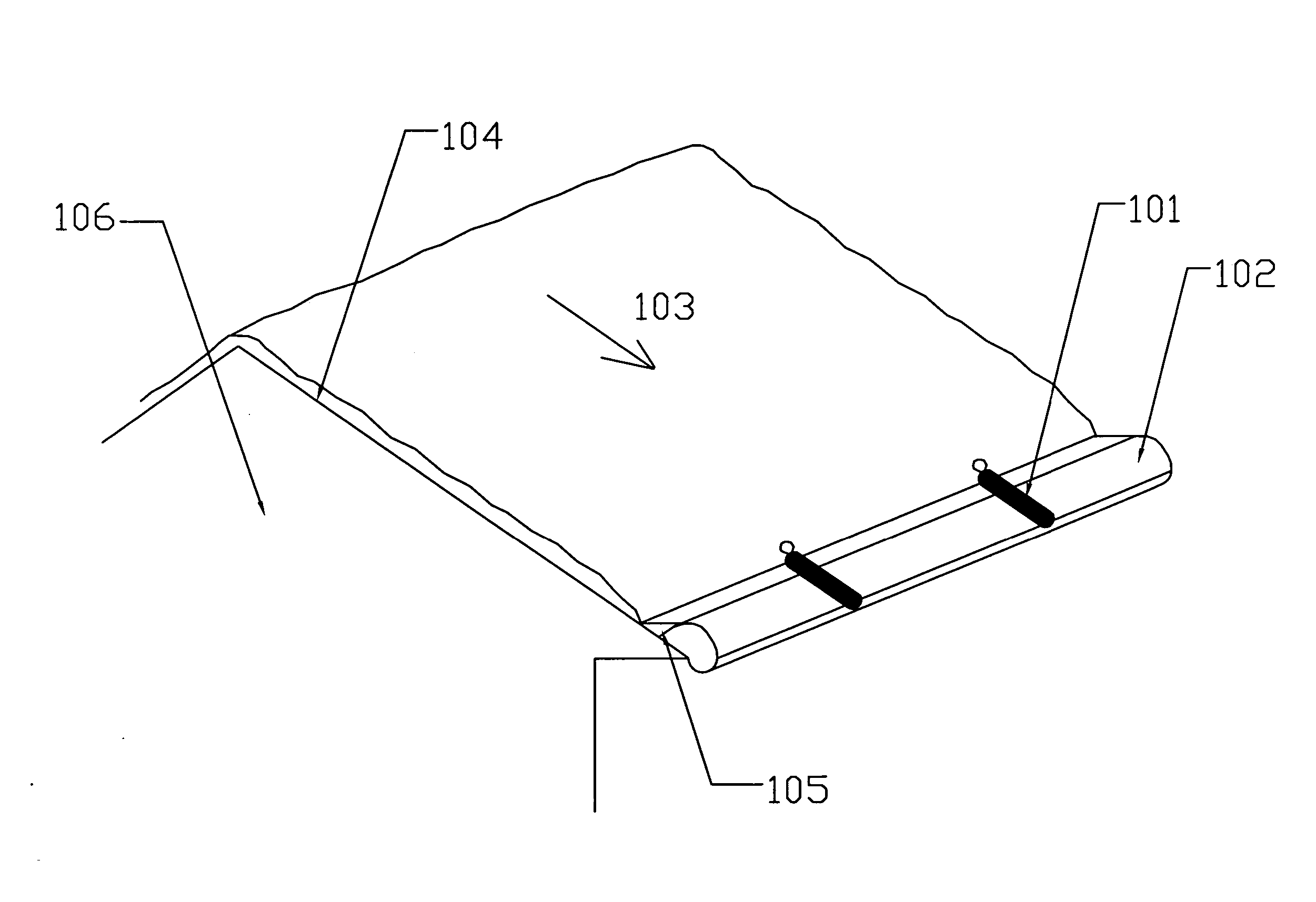
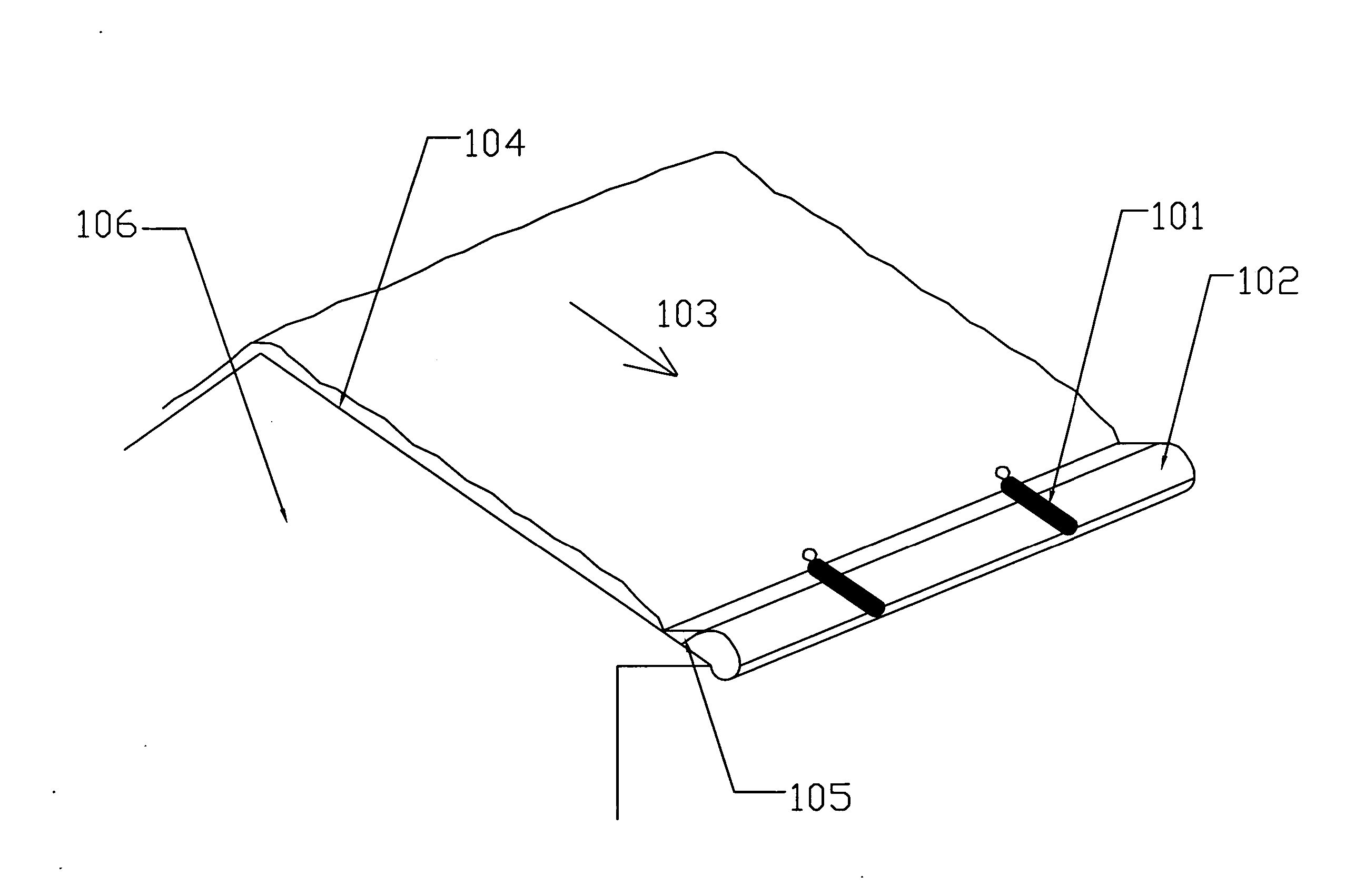
[0035] As shown in FIG. 1, in its general form, the preferred embodiment consists of an apparatus 101 that is laid across the ice dam 102, parallel to the pitch of the roof 103. Through heat or chemical action it melts the ice beneath it. By its own weight, it melts down though the ice dam 102 until it rests on the roof 104. A drainage path through the ice dam 102 is thus created directly underneath it. The liquid water 105 behind the dam 102 is thus allowed to drain and leakage of the water 105 into the house 106 is averted. Alternatively, the present invention 101 can prophylactically be placed on the roof before the ice dam 102 forms. In that case, a drainage path will be maintained and a dangerous buildup of liquid water 105 will not occur.

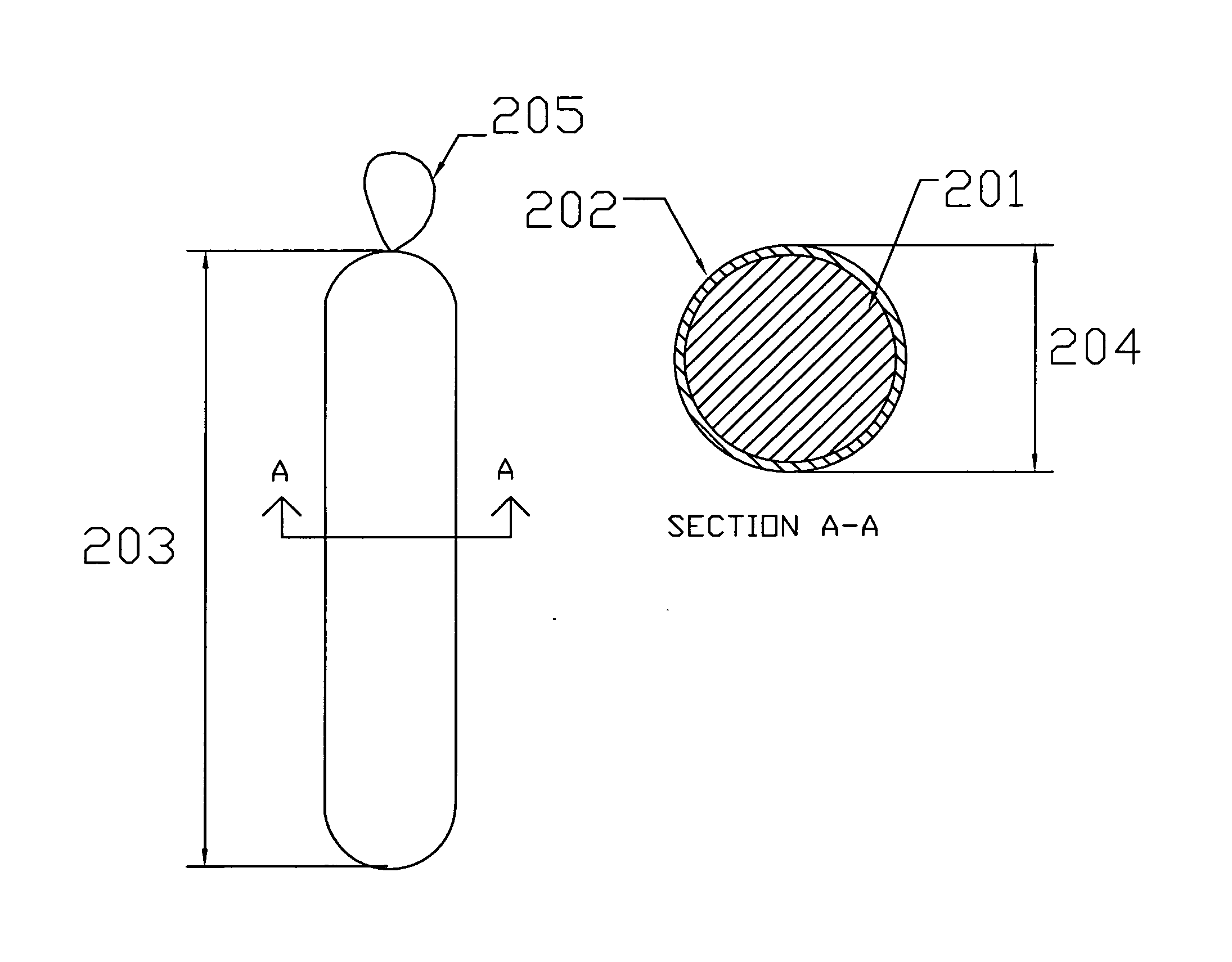
[0036] As shown in FIG. 2, in one low cost embodiment, an ice melting chemical 201 is used. In one embodiment, the chemical is enclosed in a sheath 202. This embodiment is generally cylindrical. Its length 203 can vary. It does not need to be...


PUM


Abstract

An apparatus and a method for its installation are described for melting breaches in ice dams. The apparatus is spherically or cylindrically shaped, filled with salt, another ice melter or a resistance heater. It is laid on the ice dam along the roof pitch to create a path for the drainage of water behind the ice dam. The method of installation uses grippers or hooks attached to a pole for remote placement.

Description

BACKGROUND [0001] 1. Field of the Invention [0002] The invention relates generally to a method and apparatus for preventing water buildup behind ice dams on a roof. More particularly it pertains to melting channels in the ice dam to allow the water to drain. [0003] 2. Description of the Prior Art [0004] Ice dams are created when accumulated snow on a pitched roof melts, flows down the roof and then refreezes when it reaches an area of the roof that is below freezing. The snow melts in the areas of the roof where the roof surface temperature is above freezing because of heat emanating from the building. If the ambient temperature is below freezing, sections of the roof can be below freezing and the liquid can refreeze and create an ice dam. The ice dam usually forms at the lower edge of the roof because the thermal contact between the heat emanating from the building and the roof is not as good there as the rest of the roof. [0005] It is common knowledge that ice dams can cause damag...

Claims


Application Information

Patent Timeline
IPC IPC(8): E04D13/00
CPCE04D13/103
Inventor PETROFF, CHRISTOPHER
Owner PETROFF CHRISTOPHER
Learn More