

Device for clamping a fluidic component
a fluidic component and device technology, applied in the direction of vibration suppression adjustment, hose connection, mechanical apparatus, etc., can solve the problems of inability to predict the service life of fluidic components with any reliability, difficult to generate internal tension in the elastomeric shaped part which is sufficiently great, and the known process of pressure-tight clamping of components requires considerable effort and great car
- Summary
- Abstract
- Description
- Claims
- Application Information
AI Technical Summary
Benefits of technology
Problems solved by technology
Method used
Image

Examples
example
Mount for an Atomizer Nozzle of Miniature Construction
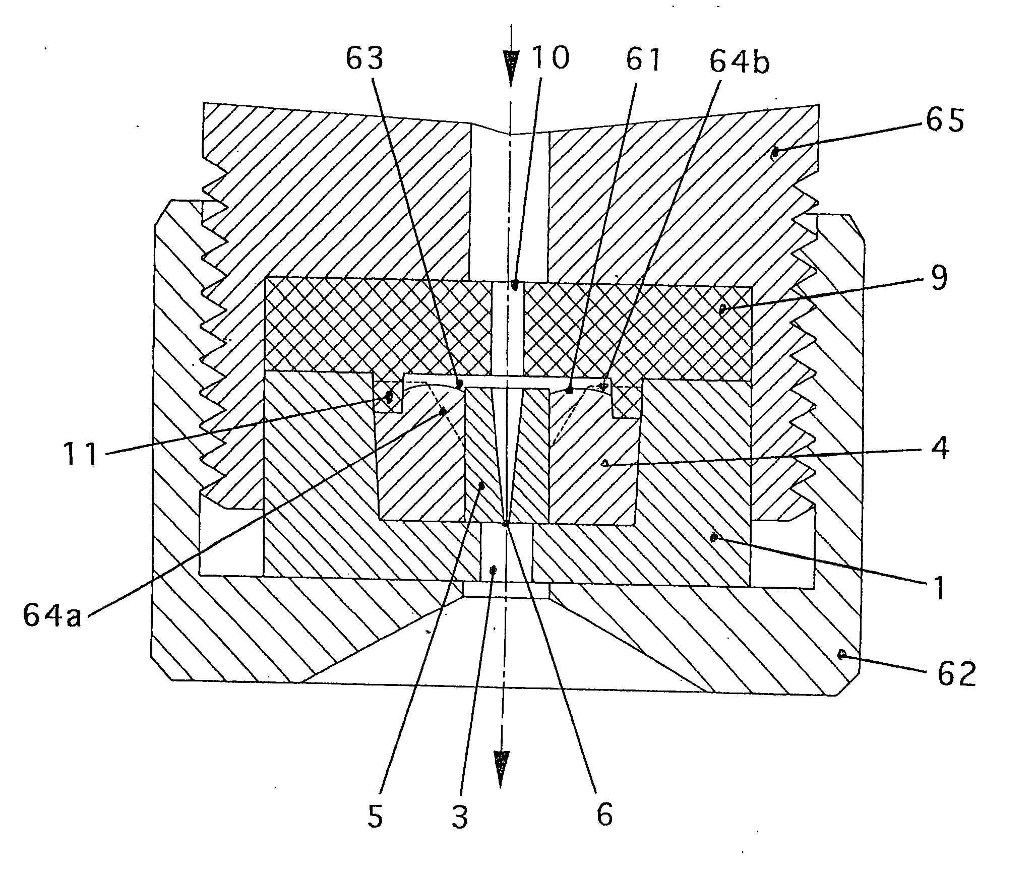
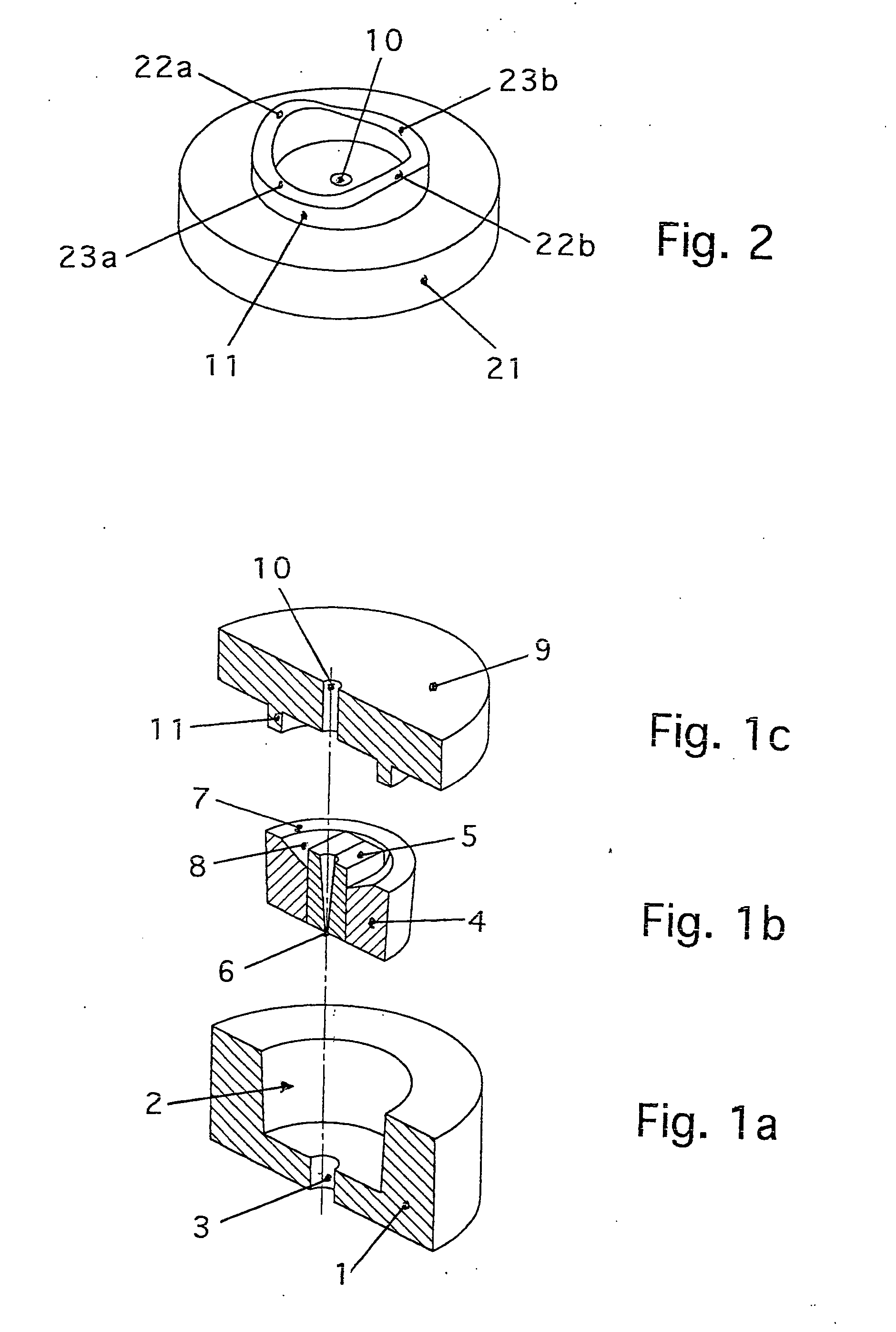
[0053] This device consists of a cylindrical holder made of steel with an external diameter of 6.0 mm and a height of 2.6 mm. It contains a truncated cone-shaped recess with an internal diameter of 4.0 mm at the base of the truncated cone. The base of the holder contains a bore 0.8 mm in diameter. The base of the holder is 0.4 mm thick in the vicinity of the bore.
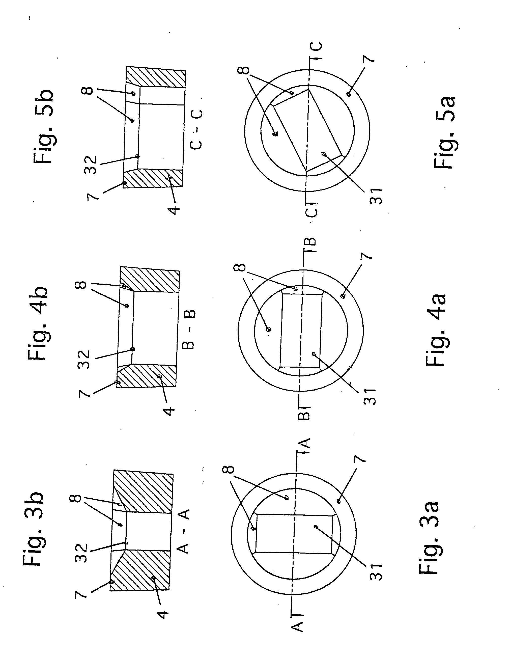
[0054] The outer contour of the elastomeric shaped part made of silicon rubber is cylindrical. Before it is inserted in the holder the cylinder has a diameter of 4.2 mm and is 2.1 mm high on its outer surface. It contains a symmetrically arranged recess 1.3 mm wide and 2.8 mm long which passes axially through the elastomeric shaped part.
[0055] The elastomeric shaped part is chamfered towards the recess at its high pressure end. The chamfer begins in the cover surface of the cylinder over a circle with a diameter of 3.2 mm. The chamfer runs at different inclinations to...
PUM
| Property | Measurement | Unit |
|---|---|---|
| mean diameter | aaaaa | aaaaa |
| height | aaaaa | aaaaa |
| diameter | aaaaa | aaaaa |
Abstract
Description
Claims
Application Information