Light brightness controller for an optical mouse

a controller and optical mouse technology, applied in the field of optical mouse, can solve the problems of inability to perform motion detection by prior optical mouse, inability to meet current standard limit,

Inactive Publication Date: 2005-09-08
SUNPLUS TECH CO LTD
View PDF2 Cites 14 Cited by
  • Summary
  • Abstract
  • Description
  • Claims
  • Application Information

AI Technical Summary

Benefits of technology

[0009] An object of the invention is to provide a light brightness controller for an optical source, w

Problems solved by technology

In addition, the light source 210 requires longer lighting time at suspend (current standard limit for USB Suspend to 500 μA), so that the c

Method used


Image

  • Light brightness controller for an optical mouse
  • Light brightness controller for an optical mouse
  • Light brightness controller for an optical mouse

Examples


Embodiment Construction

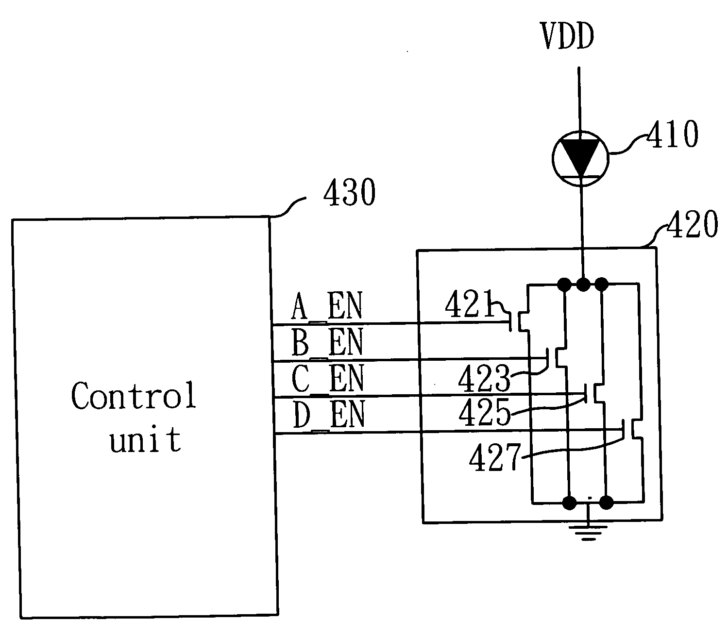
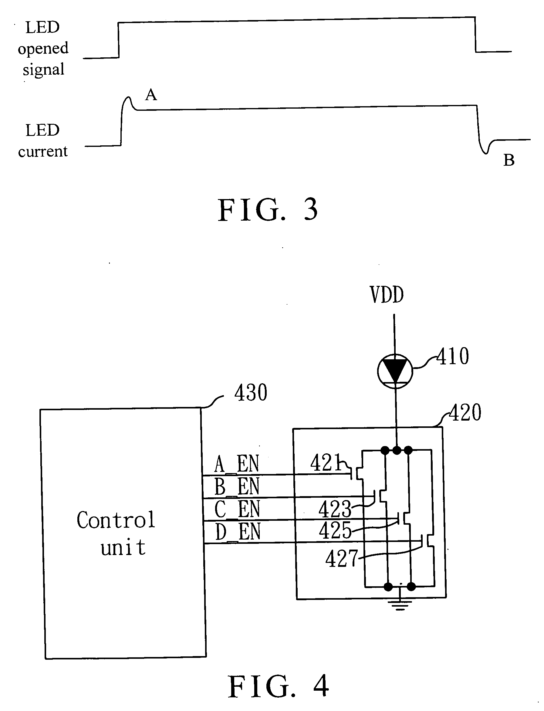
[0024]FIG. 4 is a block diagram of an embodiment of a light brightness controller for an optical mouse in accordance with the invention. In FIG. 4, the controller includes a light source 410, a current switch 420 and a control unit 430. The light source 410 is preferably an LED. The LED 410 illuminates a sampling plane of the optical mouse, and has a positive electrode connected to a high potential and a negative electrode connected to the current switch 420. The current switch 420 has a plurality of switches respectively connected to the light source 410 for providing the light source 410 with a current to flow therethrough as one of the switches is turned on. The control unit 430 is connected to the current switch 420 for controlling the current flowing through the light source 410 by controlling the switches on and off.

[0025] As shown, the switches consist of NMOSs 421, 423, 425 and 427. The NMOSs 421, 423, 425 and 427 respectively have a drain connected to the negative electrod...


PUM


Abstract

A light brightness controller for an optical mouse, which has a light source, a current switch and a control unit. The light source illuminates a sampling plane of a mouse. The current switch has a plurality of switches respectively connected to the light source such that the control unit connected to the current switch can control an amplitude of current flowing through the light source by turning the switches on and off, thereby controlling a brightness of the light source.

Description

BACKGROUND OF THE INVENTION [0001] 1. Field of the Invention [0002] The invention relates to the technical field of an optical mouse and, more particularly, to a light brightness controller for an optical mouse. [0003] 2. Description of Related Art [0004] Typically, an optical mouse uses a light emitted diode (LED) to illuminate a pad or other object and an image sensor to obtain image frames on the pad for comparing a previous and a current images and obtaining a motion vector of the optical mouse. FIG. 1 is a block diagram of the optical mouse, which includes a light source 210, a resistor 220 and an optical processor 230. The light source 210 is an LED to vary current flowing through the light source 210 by the resistor 220, thereby determining the brightness of the light source 210. There are two types where a frame signal indicates a start or synchronous signal of each image frame for controlling lighting of the LED, as shown in FIG. 2 illustrating a control timing diagram of l...

Claims


Application Information

Patent Timeline
IPC IPC(8): G09G5/08
CPCG06F3/03543G06F3/0317
Inventor LIN, CHIA-CHUN
Owner SUNPLUS TECH CO LTD
Why Eureka
Try Eureka