Email confirmation for specified task at print device

a technology of e-mail confirmation and task, applied in the field of multi-functional devices and printers, can solve problems such as loss of productivity for users

Inactive Publication Date: 2005-09-08
LEXMARK INT INC
View PDF25 Cites 16 Cited by
  • Summary
  • Abstract
  • Description
  • Claims
  • Application Information

AI Technical Summary

Benefits of technology

[0010] An advantage of the present invention is that a user is provided with an email confirmation indicating success or failure of a specified task to be carried out at a print device.
[0011] Another advantage is that a thumbnail image of rendered image data associated with the specified task may also be provided to the user.
[0012] Yet another advantage is that additional information pertaining to an attached rendered image data file is also provided to the user, such as file name, data format, resolution, etc.

Problems solved by technology

This can be frustrating and can result in lost productivity for the user.

Method used


Image

  • Email confirmation for specified task at print device
  • Email confirmation for specified task at print device
  • Email confirmation for specified task at print device

Examples


Embodiment Construction

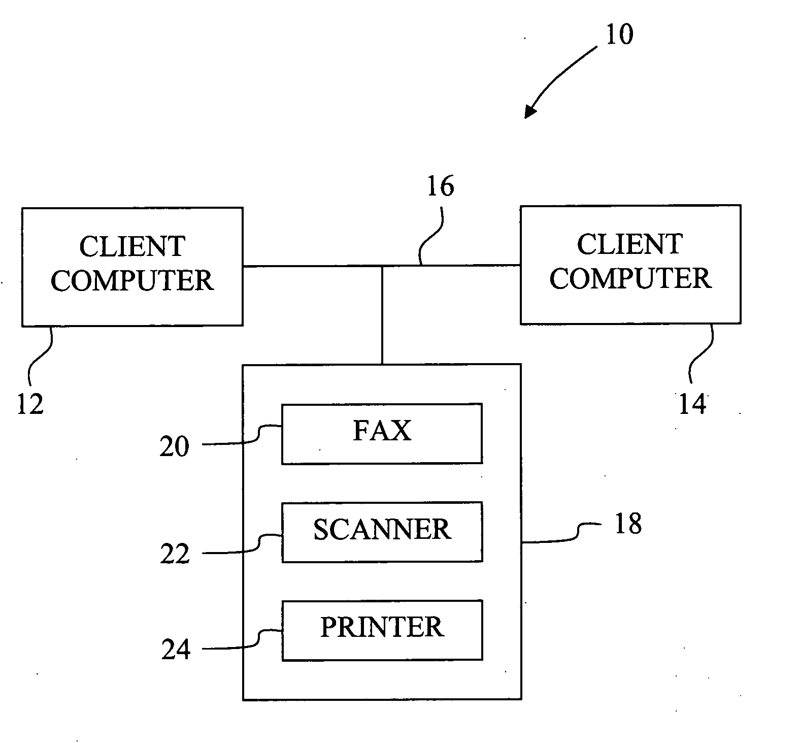
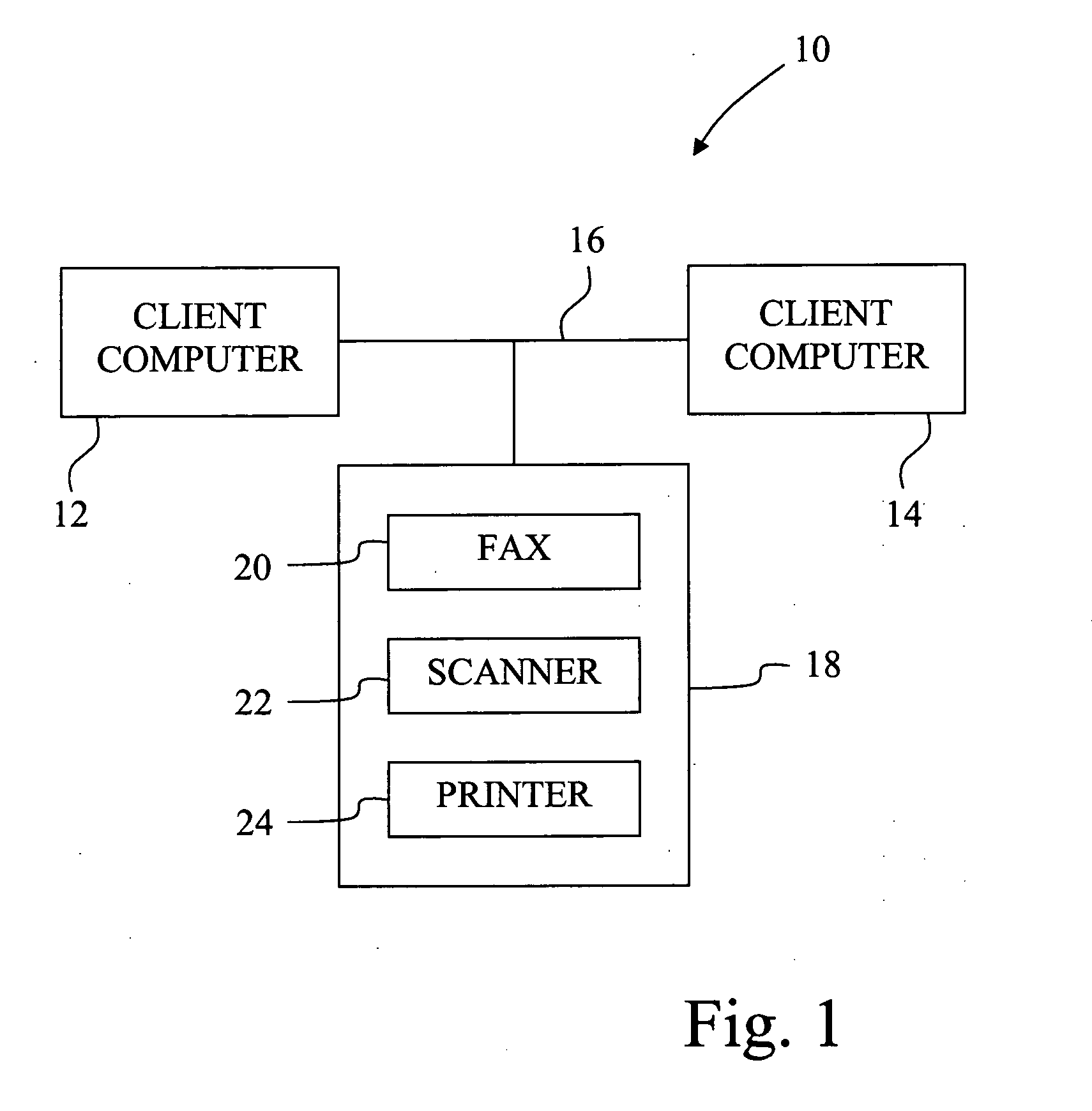
[0018] Referring now to the drawings, and particularly to FIG. 1, there is shown an embodiment of computer system 10, which may be used for carrying out an embodiment of a method of using a printer of the present invention. Computer system 10 generally includes a client computer 12 which communicates with another client computer 14 via a network 16. Computer system 10 may also include a number of additional client computers or a server (not shown) which are likewise connected with network 16.

[0019] Client computers 12 and 14 are also coupled with a multifunction machine (MFM) 18. MFM 18 has multiple functional components, including fax or fax component 20, scanner or scanner component 22 and printer or printing component 24. Printer 24 provides MFM 18 with printing capabilities; and thus MFM 18 can broadly be termed a “print device” or “printing apparatus.” Printer 24 may be any suitable type of printing component, such as an ink jet printer, laser printer, etc. Moreover, printer 2...


PUM


Abstract

A method of using a print device, includes the steps of: carrying out a specified task at a print device; and generating an email confirmation including an indication of success or failure of the carried out task at the print device.

Description

BACKGROUND OF THE INVENTION [0001] 1. Field of the Invention [0002] The present invention relates to printers and multifunction devices, and, more particularly, to a method of using such devices attached to a network. [0003] 2. Description of the Related Art [0004] Client computers are commonly connected with each other and with a server over a network. A client computer may be directly connected to a peripheral device, such as a multi-function machine, which includes printer, scanner, facsimile and copier functions. Alternatively, the peripheral device may be coupled to the network for communication with one or more of the client machines. [0005] The scanner and fax components or units of the multi-function machine may both be used as input devices for the creation of an image data file containing image data which is to be transmitted over the network to a client computer. In the case of a network connected machine, a user may place a page to be scanned on the multi-function machin...

Claims


Application Information

Patent Timeline
Patent Type & Authority Applications(United States)
IPC IPC(8): G06F15/00
CPCG06F3/1207G06F3/1259G06F3/1273H04N2201/0017H04N1/00212H04N1/00222G06F3/1285
Inventor BRIDGES, AMANDA K.FLOWERS, WILLIAM J.G.GRIESHABER, CHARLES E.TIMPERMAN, MICHAEL R.TURBEK, MILAMARIA S.
Owner LEXMARK INT INC
Why Eureka
Try Eureka