

Developing device
a technology of developing device and developing device, which is applied in the direction of electrographic process apparatus, instruments, optics, etc., can solve the problems of degrading printing quality, failure to form thin toner layer (on the photosensitive body), failure to charge toner in the developing device, etc., to prevent the pressure increase of toner and enhance printing quality
- Summary
- Abstract
- Description
- Claims
- Application Information
AI Technical Summary
Benefits of technology
Problems solved by technology
Method used
Image

Examples
first embodiment
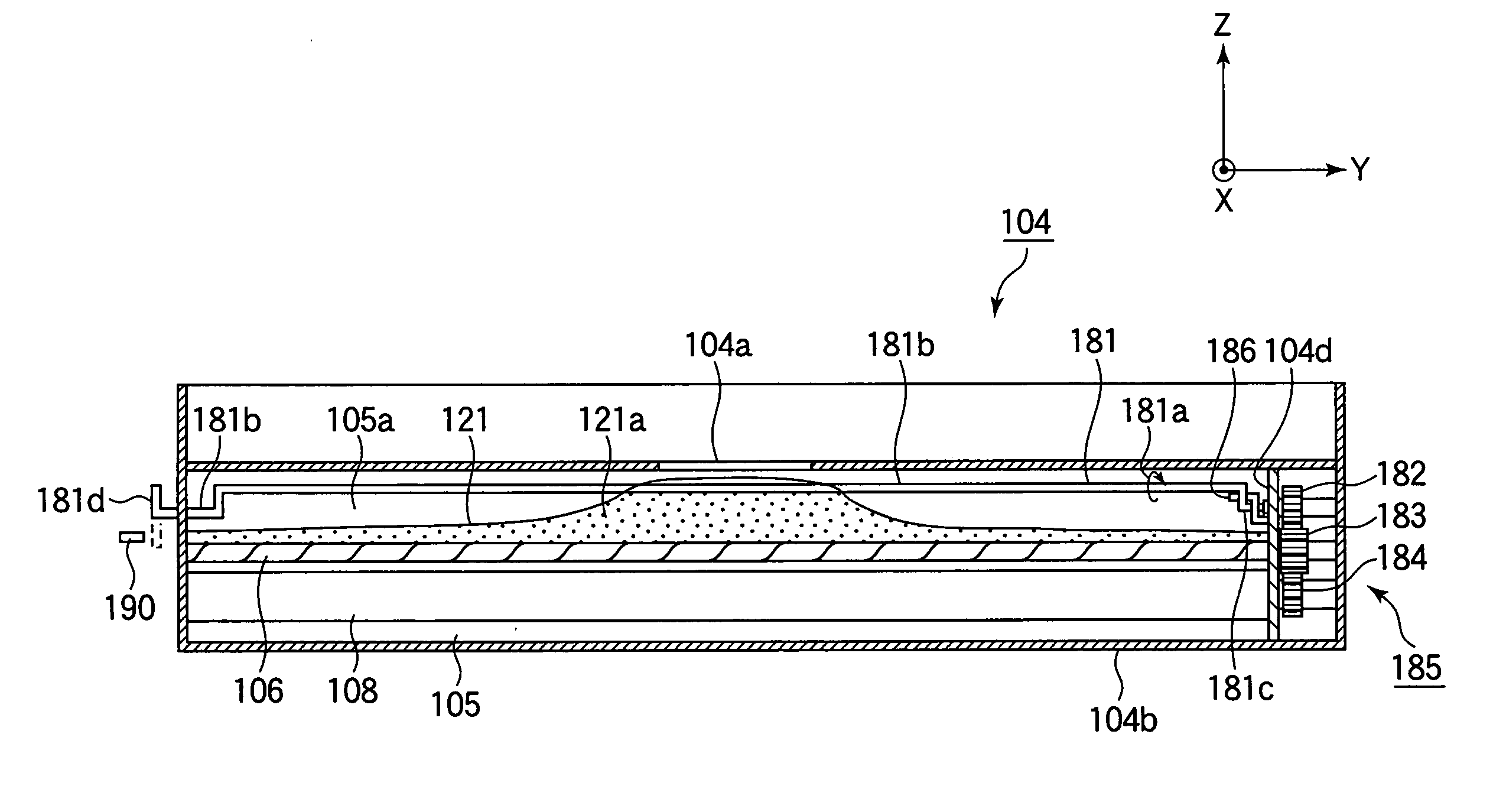
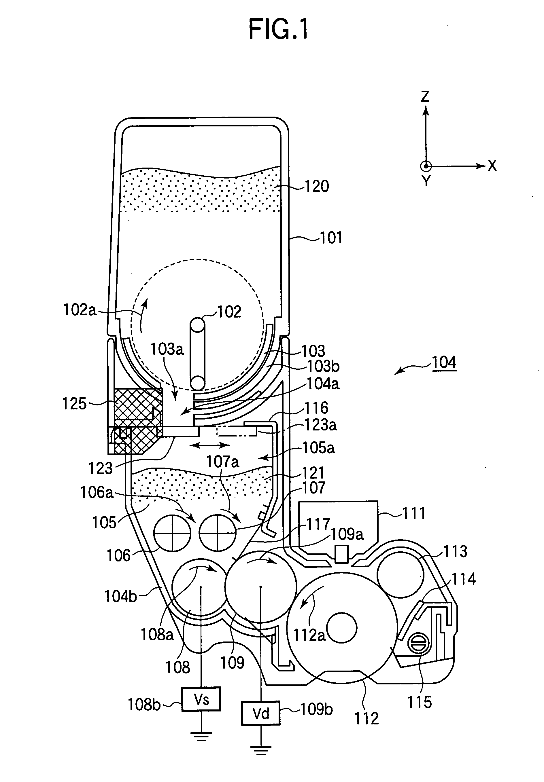
[0032]FIG. 1 is a sectional side view of a developing device according to the first embodiment of the present invention. In FIG. 1, a toner container 101 is detachably attached to the top of a developing device 104. The developing device 104 is elongated in one direction. In FIG. 1, Y-axis is defined as a longitudinal direction of the developing device 104. Z-axis is defined as a vertical axis. X-axis is defined as being perpendicular to Y-axis and Z-axis.
[0033] The toner container 101 stores a toner (i.e., a developer) 120, and has a rotatable toner agitating bar 102. The toner agitating bar 102 is driven by a not shown driving source and rotates in the direction shown by an arrow 102a. A toner container 101 has a semicylindrical bottom wall 103b having a supply opening 103a through which the toner is supplied to the developing device 104. A semicylindrical toner shield wall 103 is provided on the inner side of the bottom wall 103b, and rotatable for opening and closing the supply...
second embodiment
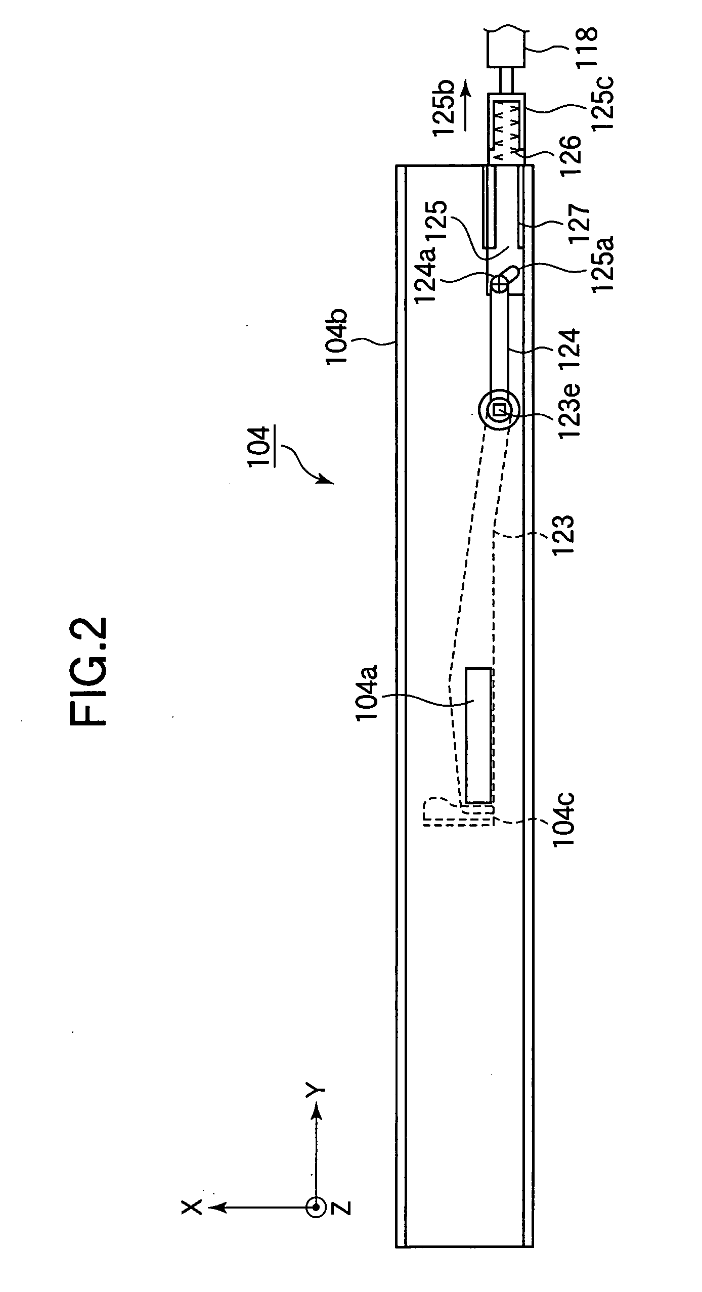
[0049]FIG. 5 is a top view of the main part of the developing device 104 according to the second embodiment. In FIG. 5, a shutter 128 of the second embodiment is made of a plate metal such as stainless steel (SUS). The shutter 128 is provided below the supply opening 104a to open and close the supply opening 104a. As was described in the first embodiment, one end (first end) of the shutter 128 is guided by the guide member 104c in the direction of X-axis, and the other end (second end) of the shutter 128 is connected to the lever 124. A projection 128e is formed on the second end of the shutter 128, and projects outside the developing device 104 in the direction of Z-axis. The projection 128e functions as a fulcrum of the shutter 128 and the lever 124, so that the shutter 128 and the lever 124 rotate together with each other with no phase difference.
[0050] As in the first embodiment, the lever 124 has the projection 124a formed on the opposite end to the projection 128e. The projec...
third embodiment
[0054]FIG. 7 is a sectional side view of the developing device 104 according to the third embodiment. FIG. 8 is a top view of the main part of the developing device 104 according to the third embodiment. As shown in FIGS. 7 and 8, a shutter 140 of the third embodiment is provided below the supply opening 104a to open and close the supply opening 104a. The shutter 140 includes a plate portion 140a which is knee-shaped as seen in the direction of Y-axis, and a shaft portion 142 fixed to the plate portion 140a. As shown in FIG. 8, an end 141 of the shaft portion 142 projects outside the developing device 104 in the direction of Y-axis. The end 141 of the shutter 140 is fixed to the plunger of the solenoid 118, and is urged in the direction indicated by an arrow 144a.
[0055] As shown in FIG. 8, the shaft portion 142 is provided in the developing device 104. The shaft portion 142 is rotatably supported by the outer wall 104b and a fixing member 147 of the developing device 104 so that th...
PUM
 Abstract
Description
Claims
Application Information