Energy conversion and dissipation system

a technology of energy conversion and dissipation system, which is applied in the direction of positive displacement liquid engine, piston pump, fluid coupling, etc., can solve the problems of parasitic load on the vehicle system, overall efficiency loss, and energy used to drive the cooling fan

Active Publication Date: 2005-09-08
BOSCH REXROTH AG
View PDF13 Cites 9 Cited by
  • Summary
  • Abstract
  • Description
  • Claims
  • Application Information

AI Technical Summary

Problems solved by technology

Also, in many cases the energy used to drive the cooling fan is a parasitic load on the vehicle system to w

Method used


Image

  • Energy conversion and dissipation system
  • Energy conversion and dissipation system
  • Energy conversion and dissipation system

Examples


Embodiment Construction

[0014] The preferred exemplary embodiments of the present invention will now be described with the reference to accompanying drawings.

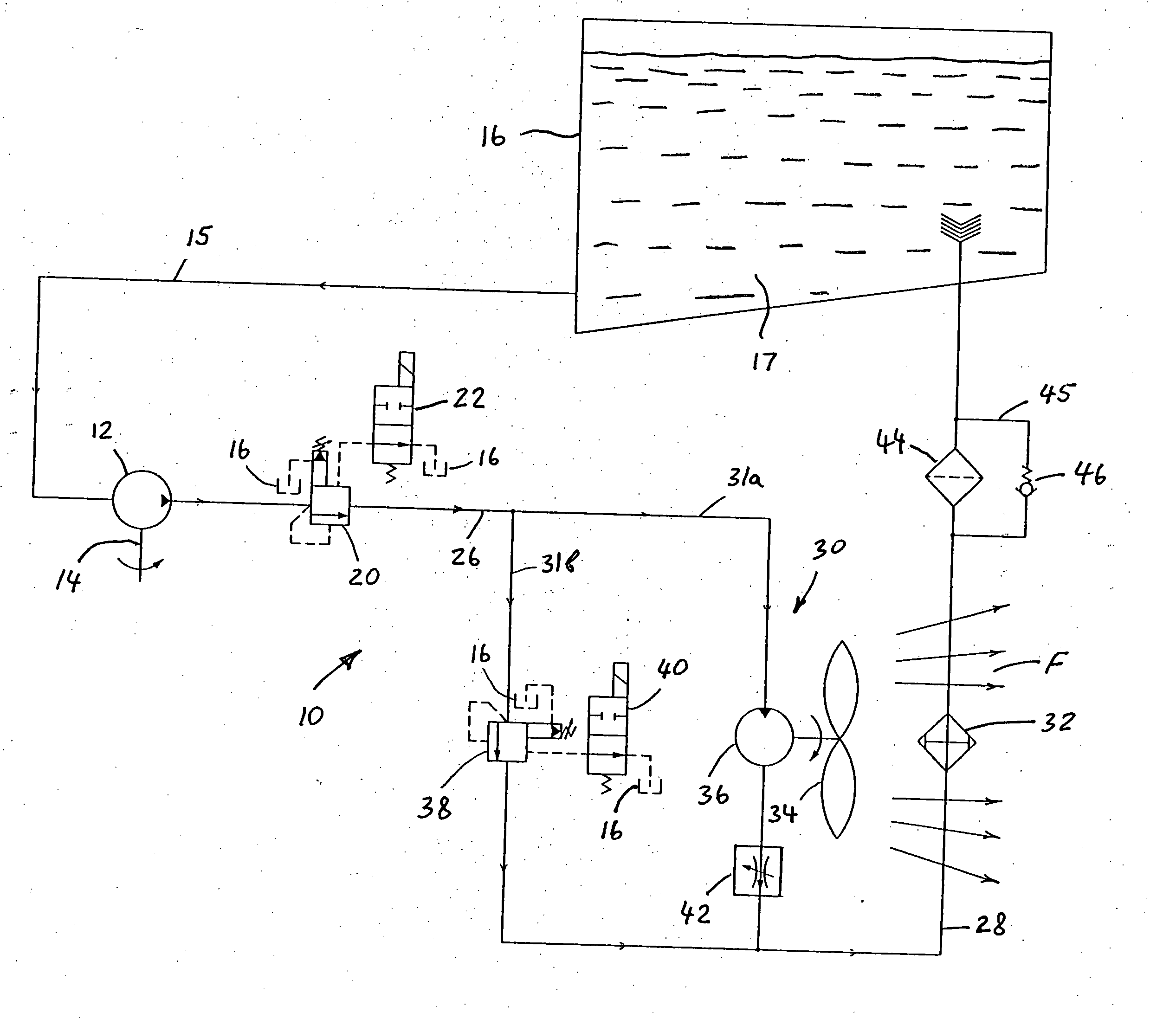
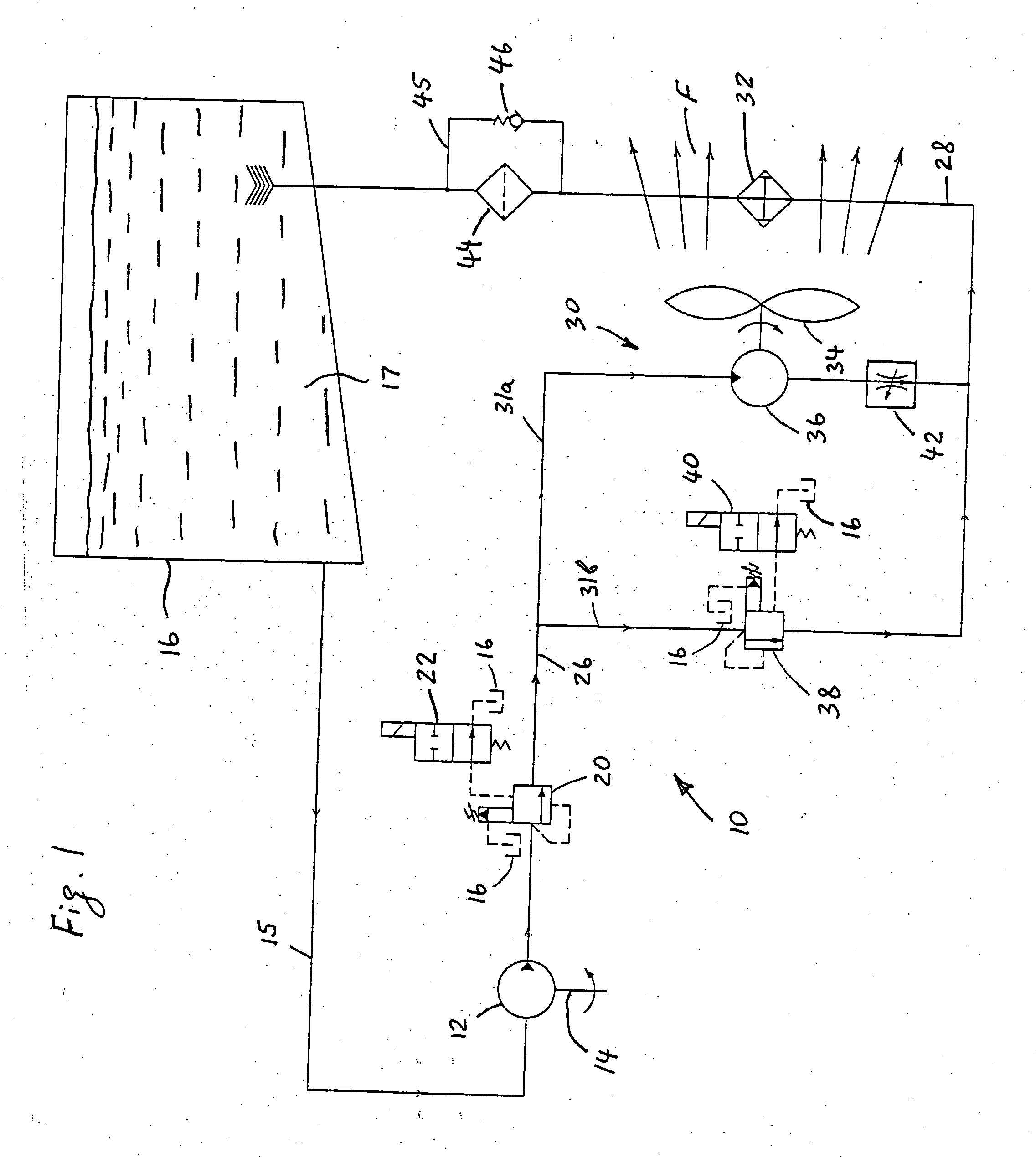
[0015]FIG. 1 schematically depicts an energy conversion and dissipation system, generally designated by the reference numeral 10, for a hydraulic retarding apparatus in accordance with a first exemplary embodiment of the present invention. The conversion and dissipation system 10 comprises a primary retarder hydraulic pump 12 and a heat dissipation system 30. The mechanical energy retarding apparatus of the present invention may be employed in various applications including but not limited to hydraulic retarding or hydraulic regenerating braking systems of motor vehicles. In such an application, the primary retarder hydraulic pump 12 is connected to a driveline of a motor vehicle through a shaft 14. Moreover, if the conversion and dissipation system 10 is used in the hydraulic regenerating braking system, the primary retarder hydraulic pump 12 may be...


PUM


Abstract

A hydraulic energy conversion and dissipation system comprises a hydraulic retarder pump driven by a source of a mechanical energy needed to be dissipated for converting the mechanical energy into a waste hydraulic energy, a hydraulic flow retarder provided for converting the waste hydraulic energy into a thermal energy, at least one heat exchanger for dissipating the thermal energy generated by the hydraulic flow retarder and at least one cooling fan provided for producing a forced air flow through the heat exchanger. The cooling fan is driven by a corresponding hydraulic motor powered by the waste hydraulic energy of the pressurized hydraulic fluid flow generated by the hydraulic retarder pump for further dissipating the waste hydraulic energy. The system further includes a hydraulic fluid reservoir in fluid communication with an inlet of the hydraulic retarder pump.

Description

BACKGROUND OF THE INVENTION [0001] 1. Field of the Invention [0002] The present invention relates to hydraulic retarding apparatuses in general and, more particularly, to a hydraulic energy dissipation system for a hydraulic, mechanical energy retarding apparatus. [0003] 2. Description of the Prior Art [0004] In a typical hydraulic energy dissipation system of a hydraulic retarding apparatus, pressurized hydraulic fluid generated by a mechanical energy needed to be dissipated flows across a certain restriction. As the fluid flows across this restriction, there is a pressure drop while the flow remains constant. This drop in pressure represents a decrease in the hydraulic potential energy. In the absence of any mechanical work being done, the change in hydraulic potential energy results in an increase in a thermal (or heat) energy of the hydraulic fluid as it passes through the restriction. [0005] Typically, this heat energy is dissipated into the environment through the use of an ai...

Claims


Application Information

Patent Timeline
IPC IPC(8): B60T1/093B60T10/04
CPCB60T10/04B60T1/093
Inventor ROSE, KENRIC B.
Owner BOSCH REXROTH AG
Why Eureka
Try Eureka