
Perpendicular magnetic recording medium

a magnetic recording medium and perpendicular technology, applied in the field of perpendicular magnetic recording medium, can solve the problem of insufficient establishment of uniform crystalline orientation

Inactive Publication Date: 2005-09-08
SHOWA DENKO KK
View PDF22 Cites 4 Cited by
  • Summary
  • Abstract
  • Description
  • Claims
  • Application Information

AI Technical Summary

Benefits of technology

[0007] It is accordingly an object of the present invention to provide a multilayered structure film contributing to reduction in the thickness of the non-magnetic orientation controller layer underneath the magnetic crystalline layer. It is an object of the present invention to provide a multilayered structure film contributing to improvement in the characteristic of electromagnetic transduction of a perpendicular magnetic recording medium.
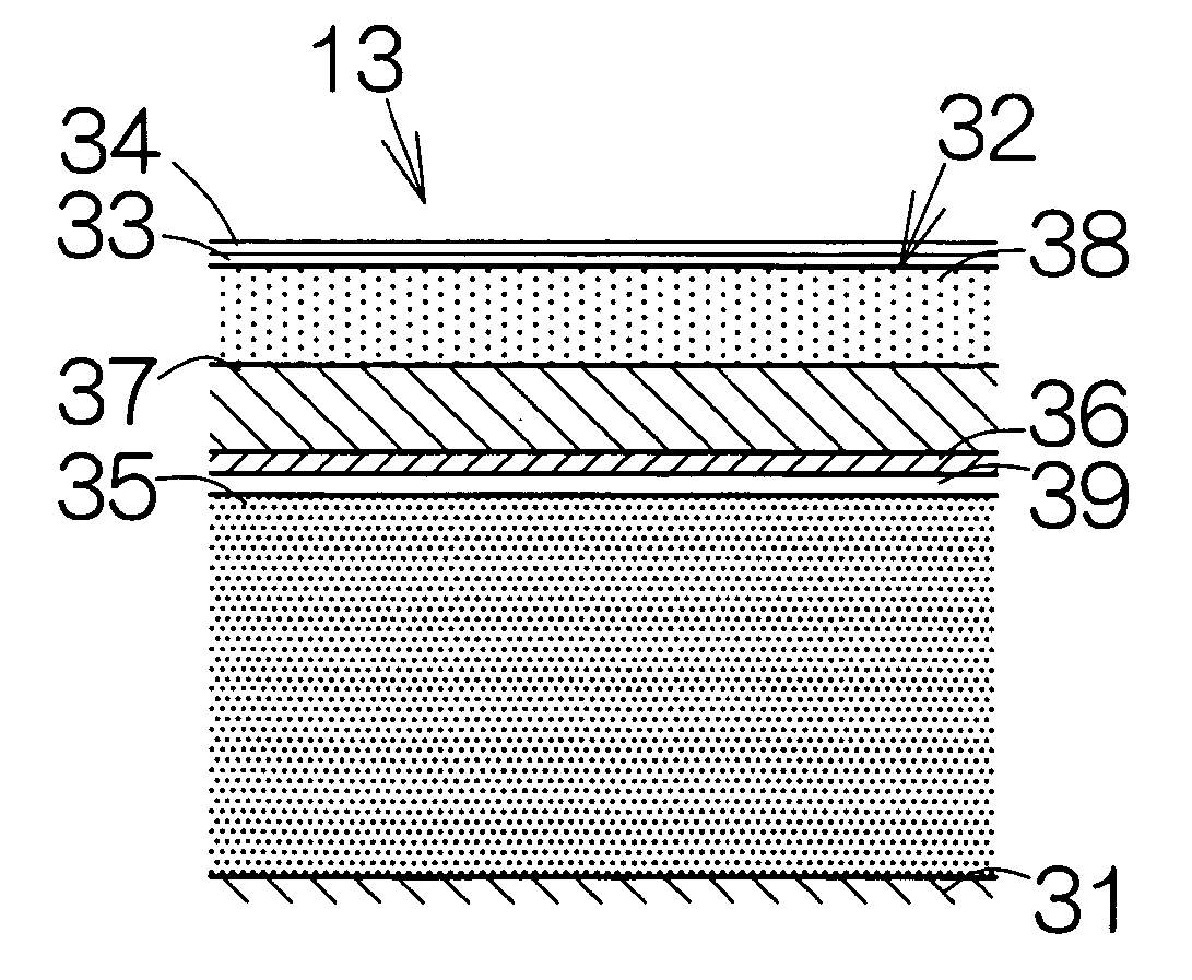
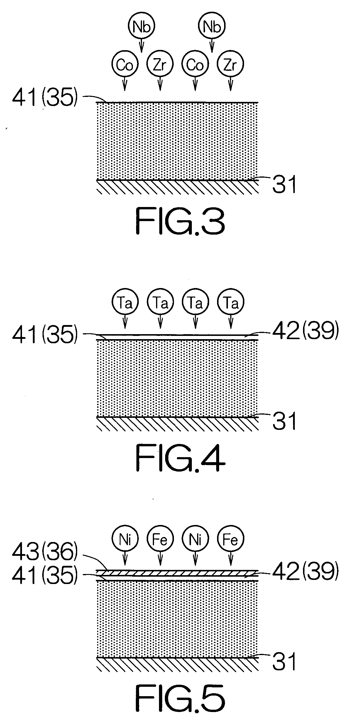
[0009] The perpendicular magnetic recording medium allows a reliable establishment of a uniform crystalline orientation based on the influences from the magnetic and non-magnetic orientation controller layers. The crystalline orientation can reliably be controlled in the magnetic recording layer as compared with the case where the non-magnetic orientation controller layer is solely employed to control the crystalline orientation in the magnetic recording layer. The axes of easy magnetization can thus reliably be aligned in the direction perpendicular to the surface of the magnetic recording layer in the individual crystalline grains in the magnetic recording layer. The perpendicular magnetic recording medium enjoys a higher performance in the property of electromagnetic transduction. In addition, a reliable establishment of a uniform crystalline orientation can be achieved without an increase in the thickness of the non-magnetic orientation controller layer.
[0010] The perpendicular magnetic recording medium may further comprise a soft magnetic underlayer spaced from the magnetic recording layer across the magnetic and non-magnetic orientation controller layers. In this case, if the axis of easy magnetization is aligned in the direction in parallel with the surface of the soft magnetic underlayer in the magnetic orientation controller layer, the magnetic orientation controller layer also functions as a soft magnetic underlayer in combination with the soft magnetic underlayer. A distance can thus be reduced between the soft magnetic underlayer and a write head or an electromagnetic transducer. This reduced distance contributes to establishment of sharp recording bits in the magnetic recording layer.
[0014] Here, any one of a cubic structure and a tetragonal structure may be established in the crystalline grains in the non-magnetic orientation controller layer. In the case where the crystalline grains of a cubic structure are employed in the non-magnetic orientation controller layer, the epitaxy in the non-magnetic orientation controller layer based on the crystalline grains in the magnetic orientation controller layer allows the (100) planes of the crystalline grains to preferentially be oriented in the direction parallel to the surface of the non-magnetic orientation controller layer in the non-magnetic orientation controller layer. If the crystalline grains in the magnetic recording layer grow from the crystalline grains in the non-magnetic orientation controller layer of the type based on the epitaxy, the C-axes of the crystalline grains, corresponding to the axes of easy magnetization, can be aligned in the direction perpendicular to the surface of the substrate in the magnetic recording layer. In the case where the crystalline grains of a tetragonal structure are employed in the non-magnetic orientation controller layer, the epitaxy in the non-magnetic orientation controller layer based on the crystalline grains in the magnetic orientation controller layer allows the (001) planes of the crystalline grains to preferentially be oriented in the direction parallel to the surface of the non-magnetic orientation controller layer in the non-magnetic orientation controller layer. If the crystalline grains in the magnetic recording layer grow from the crystalline grains in the non-magnetic orientation controller layer of the type based on the epitaxy, the C-axes of the crystalline grains, corresponding to the axes of easy magnetization, can be aligned in the direction perpendicular to the surface of the substrate in the magnetic recording layer.
[0017] The multilayered structure film allows a reliable establishment of a uniform crystalline orientation in the crystalline layer. The crystalline orientation can reliably be controlled in the crystalline layer as compared with the case where the non-magnetic orientation controller layer is solely employed to control the crystalline orientation in the crystalline layer. A reliable establishment of a uniform crystalline orientation can be achieved without an increase in the thickness of the non-magnetic orientation controller layer.

Problems solved by technology

A reduced thickness of the non-magnetic orientation controller layer induces a failure in sufficient establishment of the uniform crystalline orientation in the magnetic recording layer.

Method used


Image

  • Perpendicular magnetic recording medium
  • Perpendicular magnetic recording medium
  • Perpendicular magnetic recording medium

Examples


Embodiment Construction

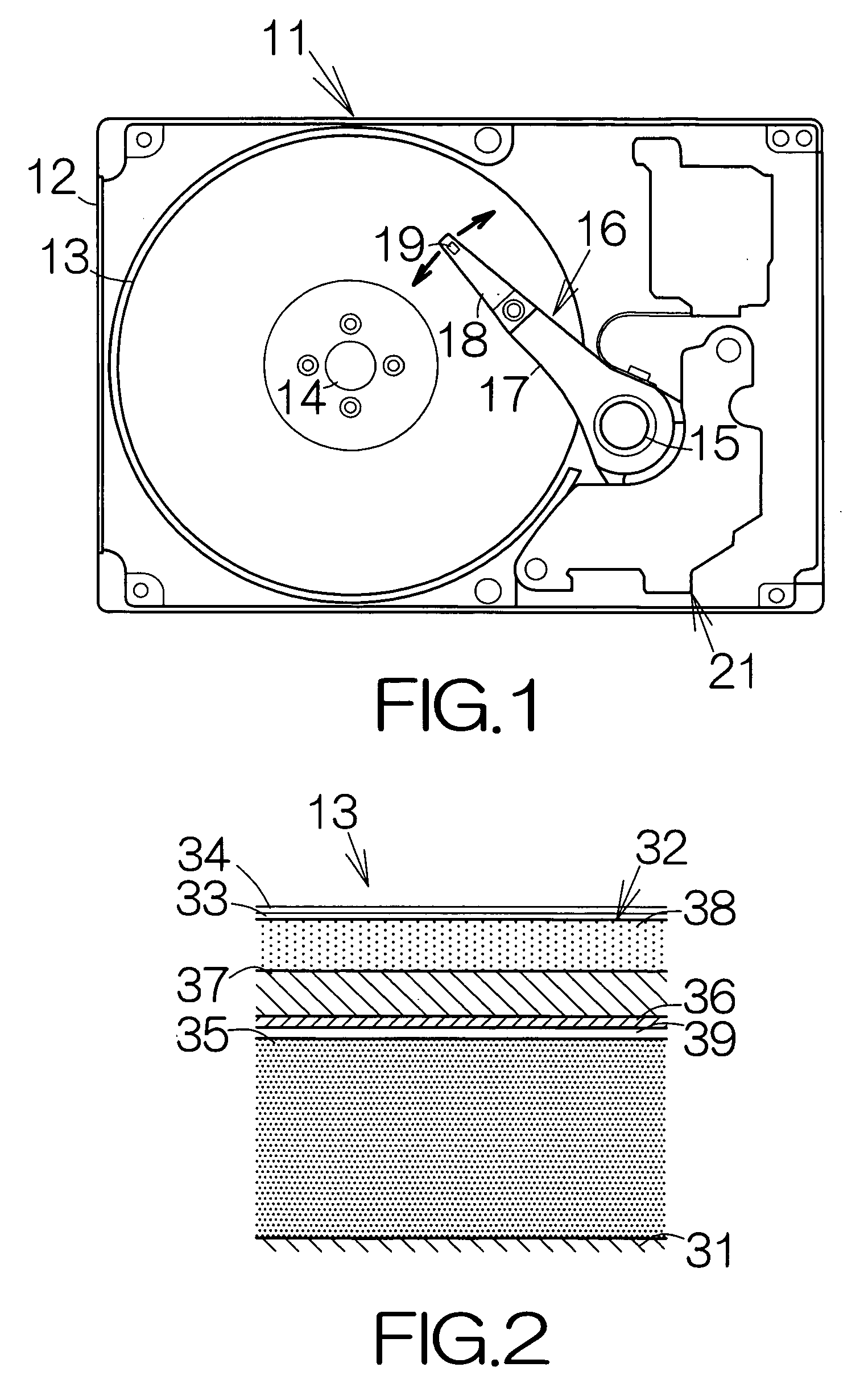
[0027]FIG. 1 schematically illustrates the interior structure of a hard disk drive (HDD) 11 as an example of a magnetic recording medium drive or storage device. The HDD 11 includes a box-shaped main enclosure 12 defining an inner space of a flat parallelepiped, for example. At least one magnetic recording disk 13 is incorporated in the inner space within the main enclosure 12. The magnetic recording disk 13 belongs to a so-called perpendicular magnetic recording medium. The magnetic recording disk or disks 13 is mounted on the driving shaft of a spindle motor 14. The spindle motor 14 is allowed to drive the magnetic recording disk or disks 13 for rotation at a higher revolution rate such as 7,200 rpm, 10,000 rpm, or the like, for example. A cover, not shown, is coupled to the main enclosure 12 so as to define the closed inner space between the main enclosure 12 and itself.

[0028] A head actuator 16 is coupled to a vertical support shaft 15. The head actuator 16 includes rigid actua...


PUM

PropertyMeasurementUnit
thicknessaaaaaaaaaa
thicknessaaaaaaaaaa
thicknessaaaaaaaaaa

Abstract

A perpendicular magnetic recording medium includes a magnetic orientation controller layer serving as a layer for controlling crystalline orientation in an upper layer. A non-magnetic orientation controller layer extends on the surface of the magnetic orientation controller layer The non-magnetic orientation controller layer serves as a layer for controlling crystalline orientation in an upper layer. A magnetic recording layer extends on the surface of the non-magnetic orientation controller layer. The perpendicular magnetic recording medium allows a reliable establishment of a uniform crystalline orientation in the magnetic recording layer based on the influences from the magnetic and non-magnetic orientation controller layers. A reliable establishment of a uniform crystalline orientation can be achieved without an increase in the thickness of the non-magnetic orientation controller layer.

Description

BACKGROUND OF THE INVENTION [0001] 1. Field of the Invention [0002] The present invention relates to a perpendicular magnetic recording medium in general utilized in a magnetic recording medium drive such as a hard disk drive (HDD). [0003] 2. Description of the Prior Art [0004] A perpendicular magnetic recording medium is well known. The perpendicular magnetic recording medium includes a so-called soft magnetic underlayer. A magnetic recording layer extends on the surface of the soft magnetic underlayer. When a write head is opposed to the magnetic recording layer, the magnetic recording layer is positioned between the write head and the soft magnetic underlayer. A circulation path is established between the write head and the soft magnetic underlayer for magnetic flux. This serves to increase the magnetic field acting on the recording magnetic layer. A sharp gradient can be ensured for the magnetic field passing through the magnetic recording layer. A sharp information bit can be e...

Claims


Application Information

Patent Timeline
Patent Type & Authority Applications(United States)
IPC IPC(8): B32B1/00G11B5/64G11B5/65G11B5/667G11B5/73
CPCG11B5/65B32B1/00G11B5/7325G11B5/667G11B5/737G11B5/676G11B5/674
Inventor INAMURA, RYOSAKUTAKESHITA, HIROTOSUGIMOTO, TOSHIOSHIMODA, KAZUMASAOSHIMA, TAKENORIMAEDA, MAKIUZUMAKI, TAKUYATANAKA, ATSUSHI
Owner SHOWA DENKO KK
Learn More