
Cascade control system for network units

a network unit and control system technology, applied in the field of communication networks, can solve the problems of increasing design difficulties, affecting the design and organisation of cascades, and affecting the design of cascades, so as to achieve the effect of improving and versatile cascade control

Active Publication Date: 2005-09-08
VALTRUS INNOVATIONS LTD +1
View PDF2 Cites 42 Cited by
  • Summary
  • Abstract
  • Description
  • Claims
  • Application Information

AI Technical Summary

Benefits of technology

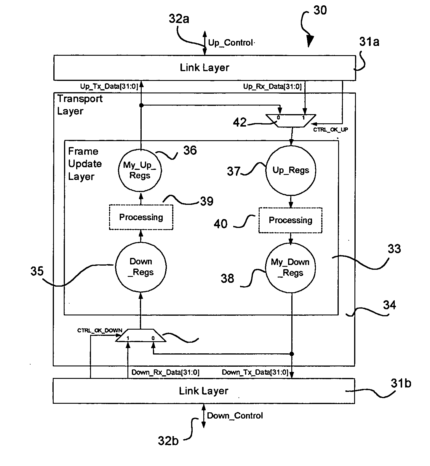
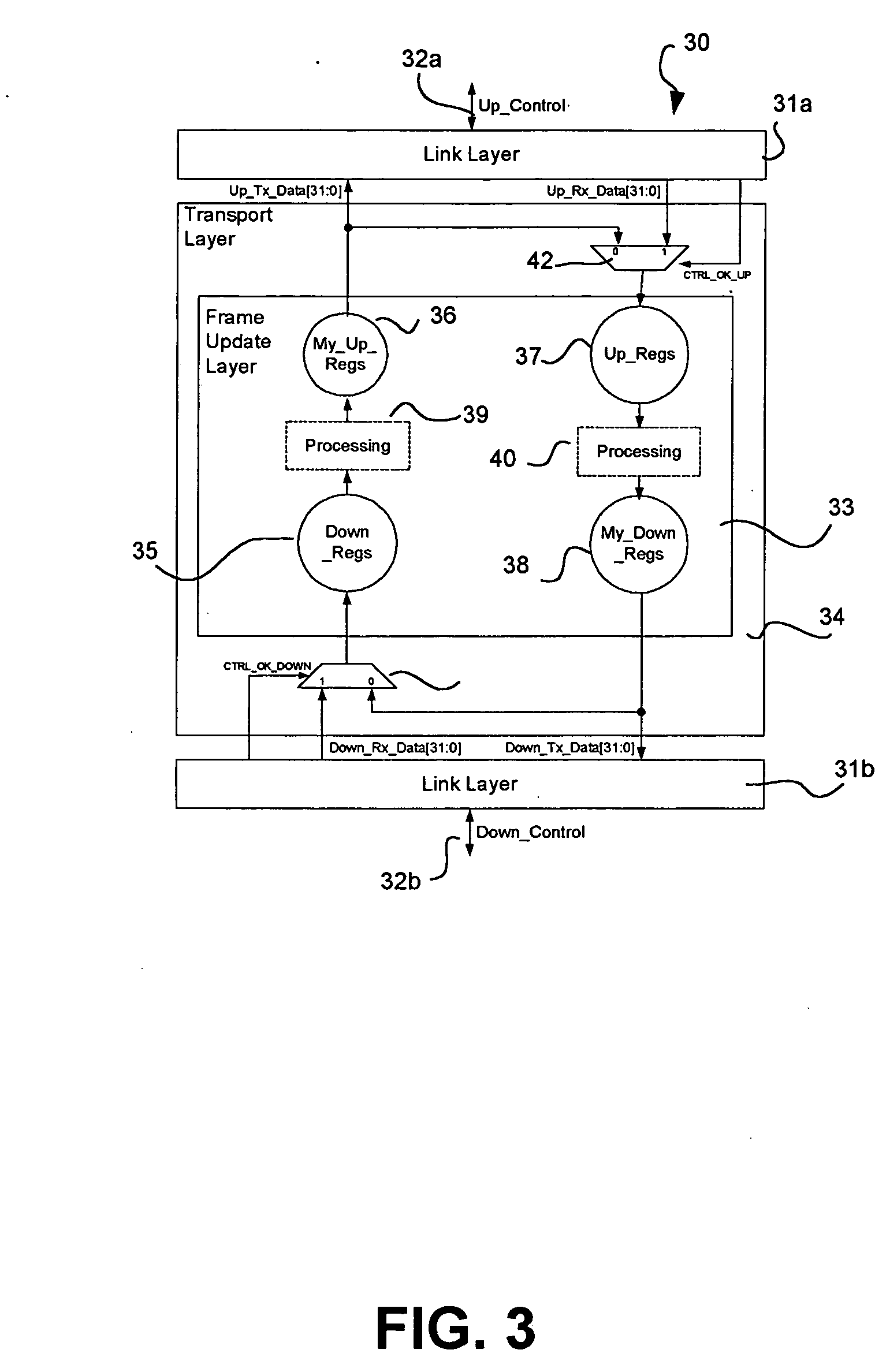
The invention provides an improved and versatile cascade control for a network unit. The network unit includes a data processor and cascade control logic for the exchange of control frames with other units in a stack. The cascade control logic is operative to automatically apply stack numbers to the units in the stack. The network unit can act as a master or slave in the cascade. The program distinguishes between units in an automatic and non-automatic numbering mode and disregards non-automatic units in the application of progressive stack numbers. The cascade control logic controls the transmission of control frames and is symmetrical relative to the up and down directions. The invention also concerns the provision of specific information to the units in the stack, the determination of a master unit for the stack, and the use of software to avoid some of the limitations of hardware.

Problems solved by technology

The design and organisation of a cascade are attended by some considerable complexity.
Although very simple cascades can be constituted by means of ordinary communication links between ports on a stack of similar or compatible devices, a variety of operational desiderata or network constraints require a cascade connection to be rather more sophisticated and produce greater difficulties in design.
However, the inclusion of control or status data relating to the units within packet headers is generally inconvenient if at all feasible.
Although the automatic numbering process is useful in the initial formation of a stack, the renumbering of units when a stack is reformed or augmented is not necessarily desirable.
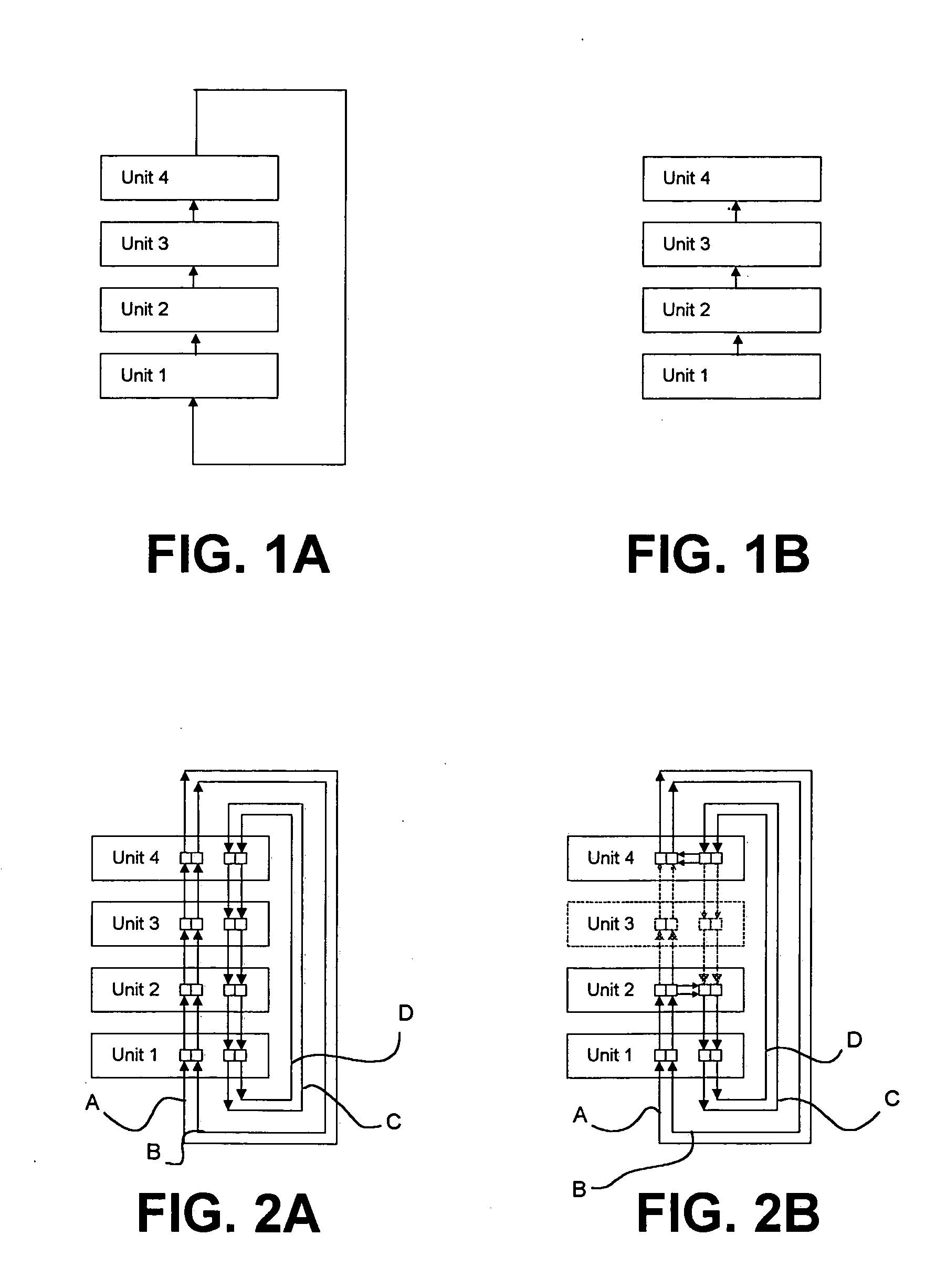
Other disadvantages of the earlier system include the provision of cascade connections as both a ‘down’ link and an ‘up’ link, and a need to employ a special cable for a ‘resilient’ connection, i.e. from the ‘top’ to the ‘bottom’ of the stack.

Method used


Image

  • Cascade control system for network units
  • Cascade control system for network units
  • Cascade control system for network units

Examples


examples

[0351]FIG. 27A illustrates a resilient stack with three units in manual assigned mode, numbered 1, 7 and 8 being denoted M1 etc to indicate the mode as well as the number. Now four ‘factory-default’ units AD (all in ‘automatic-assigned’ mode) are added into the resilient stack. The new stack is shown in FIG. 27B. It has mixed manual and automatic assignment modes. This is determined by the software from the stored indications of the mode. The fabric will remain in the manual-assigned mode and the four new units are isolated from the rest of the stack, as shown by the strike-through indications in FIG. 27C.

[0352]FIG. 28A illustrates a stack with five units in manual-assigned mode and numbered 1, 7, 8, 3 and 2. FIG. 28B shows the addition of three units in manual-assigned mode and numbered M8, M5 and M5 (a duplication of numbering). The unit with the lowest MAC address (the furthest right) is shaded. Owing to the ‘manual-assigned’ mode of the two duplicated numbers the software canno...


PUM


Abstract

A network unit for the reception and forwarding of data packets and for use in a stack of similar units includes a data processor and cascade control logic for the exchange of control frames with others of said units in the stack. The cascade control logic is operative to cooperate by means of the control frames in an automatic process for incrementally applying stack numbers to the units in the stack. The cascade control logic can retain a stack number in storage and the data processor is operative to execute a program to apply to the network unit and the other units progressive stack numbers which accommodate previously applied and retained stack numbers. The network unit can act as a master applying the program to the other units and as a slave whereupon it receives a stack number determined by another unit in the stack. The program may determine the validity of a set of numbers applied to units in the stack by computing the aggregate of numbering gaps between numbered units and comparing the aggregate with a predetermined maximum. The program distinguishes between units which are in an automatic numbering mode and a non-automatic numbering mode and disregards units in the non-automatic numbering mode in the application of progressive stack numbers.

Description

FIELD OF THE INVENTION [0001] This invention relates to communication networks. The invention specifically concerns the control of network units such as switches connected or for use in a ‘cascade’ or ‘stack’. BACKGROUND TO THE INVENTION [0002] The physical elements in a packet-based data communication system commonly include multi-port units such as switches and routers. Such units are commonly and conveniently manufactured with a fixed plurality of ports by means of which the units can be connected by way of appropriate transmission links (such as cables or optical fibres) to other units or user terminals. In order to provide greater versatility in constructing networks while minimising the number of different sizes of units that need to be deployed it is known to render the units ‘stackable’ by which is meant that a multiplicity of them can be interconnected to form effectively a single controllable entity. It is customary to make such units physically stackable in a column altho...

Claims


Application Information

Patent Timeline
Patent Type & Authority Applications(United States)
IPC IPC(8): G06F15/173H04L12/423H04L12/437H04L12/56H04Q11/04
CPCH04L12/437H04L12/423H04L12/56H04Q11/0421
Inventor SAUNDERSON, PETER A.HUTCHINGS, MICHAEL D.
Owner VALTRUS INNOVATIONS LTD
Learn More