Eureka AIR delivers breakthrough ideas for toughest innovation challenges, trusted by R&D personnel around the world.

Display panel device

Inactive Publication Date: 2005-09-15
HITACHI LTD
View PDF8 Cites 16 Cited by
  • Summary
  • Abstract
  • Description
  • Claims
  • Application Information

AI Technical Summary

Benefits of technology

[0008] An object of the present invention is to provide a structure of a display panel device that can satisfy functions easily and has good productivity.
[0010] The plane sizes of the plural layers are made the same as each other, and only one or no layer is permitted to have a nonuniform pattern, so that a method of winding plural films drawn out of plural rolls being put together on another roll (a roll-to-roll method) can be used for manufacturing the front portion. In the roll-to-roll method, a precise alignment is not required if the widths of the plural band-like films to be overlapped are made the same each other, so that multilayered film can be manufactured efficiently. In addition, plural sheets of a predetermined size can be obtained by one cut. The roll-to-roll method is suitable for laminated plural layers each of which has a thickness of 500 μm or less.
[0011] A plane size of the rear portion is smaller than that of the front portion, and the rear portion is arranged at the rear side of the front portion, so that the alignmnet accuracy required between the front portion and the rear portion can be relieved. It is because misalignment cannot be conspicuous. In particular, if translucency of the peripheral area of the front portion is low, the rim of the rear portion is hidden when viewed from the front. Therefore, an appearance is not deteriorated even if the rim of the rear portion is something indefinite in shape. In this case, painting method with low accuracy of pattern can be adopted for forming the rear portion. However, it is possible to form a sheet to be the rear portion in advance, and to glue the sheet on the front portion.
[0012] If the display panel is a plasma display panel, it is necessary to shield electromagnetic waves because a drive voltage for discharge is relatively high. A film having a conductive mesh is already developed, so it is possible to incorporate an electromagnetic wave shielding layer into the front portion. When the electromagnetic wave shielding layer is arranged as a lowest layer in the front portion, the peripheral area of the electromagnetic wave shielding layer can be exposed for connection with the conductive housing, and the function of preventing reflection or glare can be assigned to the top layer of the front portion.
[0014] According to the present invention, a display panel device that can satisfy functions easily and has good productivity can be obtained.

Problems solved by technology

However, the filter plate is not suitable for a large screen of the plasma display panel because it has a large weight.
It is difficult to realize plural functions by a single layer necessary for the front face of the display panel.

Method used


Image

  • Display panel device
  • Display panel device
  • Display panel device

Examples


example 1

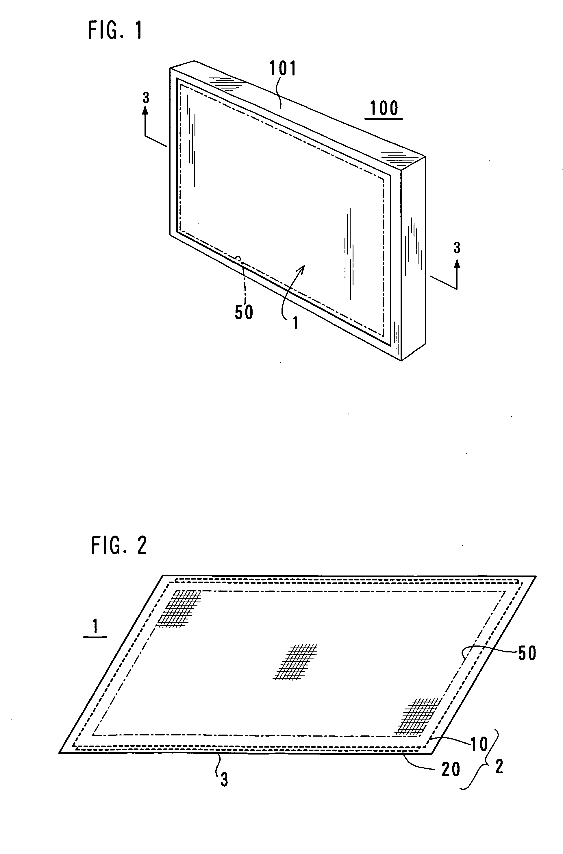
[0030]FIG. 1 shows an appearance of a display device according to the present invention. A display device 100 is a flat type display having a 42-inch diagonal screen 50. A dimension of the screen 50 is 0.92 meters in the horizontal direction and 0.52 meters in the vertical direction. A facing cover 101 that defines a plane size of the display device 100 has an opening that is larger than the screen 50, so that a front face of a display panel device 1 is exposed in part.

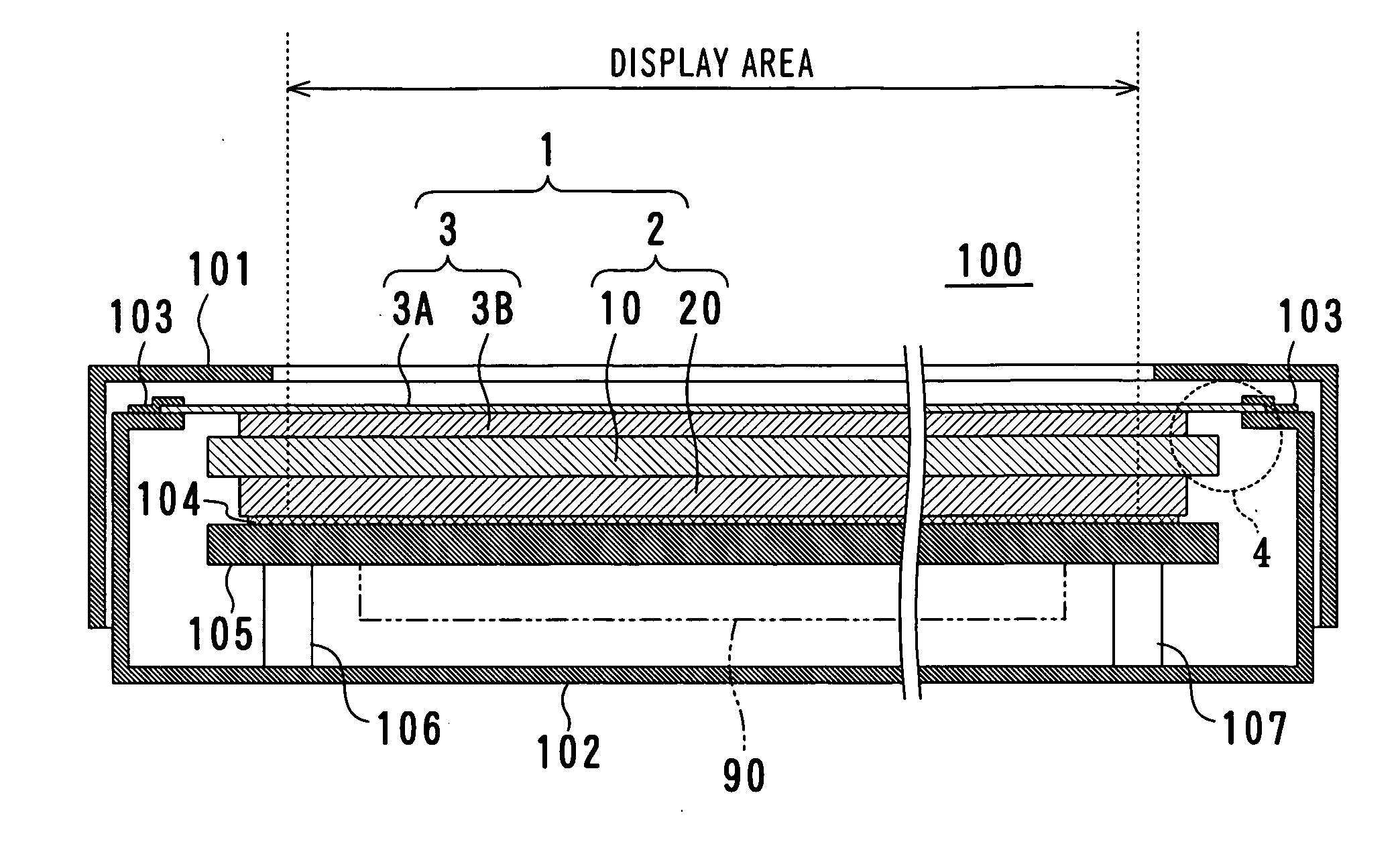
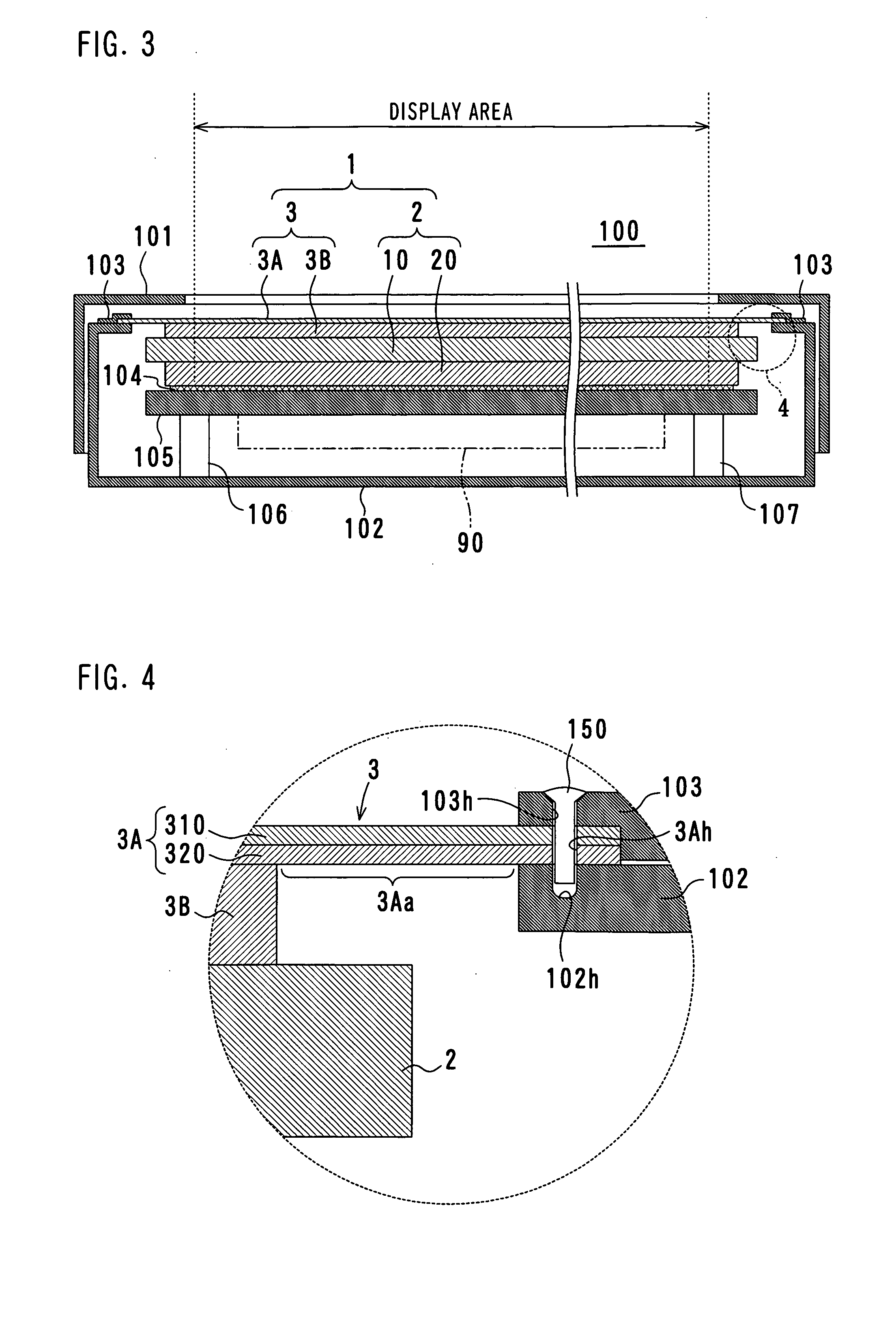
[0031]FIG. 2 shows a structure of the display panel device. The display panel device 1 includes a plasma display panel 2 that is a device that constitutes a screen and a front sheet 3 that is glued directly on the front face of the plasma display panel 2 to be a display surface. The plasma display panel 2 is a self-luminous type device that emits light by gas discharge, which includes a front face plate 10 and a rear face plate 20. Each of the front face plate 10 and the rear face plate 20 is a structural element hav...

example 2

[0053]FIG. 10 shows a second example of a structure of the display device. A basic structure of the display device 200 is the same as the above-mentioned display device 100. In FIG. 10 and the following drawings, structural elements denoted by the same reference numerals as FIG. 3 are the same as the structural elements of the display device 100.

[0054] The display device 200 includes a display panel device 5 that is a screen module. The display panel device 5 includes the plasma display panel 2 and a front sheet 6, and the front sheet 6 includes a front portion 6A and a rear portion 6B. A layer structure of the front sheet 6 is the same as shown in FIG. 6. In the display device200, a plane size of the front portion 6A is larger than the first example, and four side of the front portion 6A are bent to the rear side substantially in perpendicular manner so that the end portions of the front portion 6A are fixed to the conductive housing 202. The fixing is done by sandwiching the fron...

example 3

[0058]FIG. 12 shows a third example of a structure of the display device. A structure of the display device 300 is substantially the same as the above-mentioned display device 200. The display device 300 is characterized in that the inner rim of the front face of the facing cover 301 is close to a screen area, and sound absorbing members 351 and 352 are arranged between the facing cover 301 and the front sheet 6. The sound absorbing members 351 and 352 are glued on the facing cover 301 in advance, and the display panel device 5 is covered with the facing cover 301 so that the sound absorbing members 351 and 352 are pressed onto the front sheet 6. As the sound absorbing members 351 and 352 are flexible sponge, no excessive force is applied to the plasma display panel 2. As audible sound noises due to vibration of the plasma display panel 2 (called an abnormal sound) increases at a peripheral portion of the plasma display panel 2, the noises can be reduced substantially by arranging t...


PUM


Abstract

A front sheet that is a layered film glued on a front face of a display panel includes a front portion made of plural layers having the same plane size and different functions and a rear portion having a plane size smaller than the front portion and larger than the screen, and the rear portion is put on the front face of the display panel.

Description

BACKGROUND OF THE INVENTION [0001] 1. Field of the Invention [0002] The present invention relates to a display panel device including a flat display panel and a front sheet that is glued on the display panel. [0003] 2. Description of the Prior Art [0004] Technology development of a plasma display panel (PDP) that is a self-luminous device is directed to a large screen for providing more powerful display. One of the important tasks for a large screen is weight reduction of the panel. [0005] In general, a display device including a plasma display panel has a filter plate having a base of a tempered glass. This filter plate is arranged in front of the plasma display panel with air gap. The filter plate has various functions of adjusting a display color optically, preventing reflection of external light, shielding electromagnetic waves, and shielding near infrared rays concerning displaying operation and a function of protecting the plasma display panel mechanically. However, the filter...

Claims


Application Information

Patent Timeline
IPC IPC(8): H05K9/00G09F9/00H01J5/16H01J11/10H01J11/44H01J17/02H01J17/16H01J17/49H01J29/86H01J29/89
CPCH01J11/10H01J11/44H01J29/868H01J2329/892H01J2211/446H01J2329/869H01J29/896B07B1/22B07B1/42B07B11/02B07B11/06
Inventor KAWANAMI, YOSHIMIHORI, NOBUYUKIOHSAWA, ATSUONAMIKI, FUMIHIRO
Owner HITACHI LTD
Why Eureka
Eureka Blog
Learn More