Retrodirective noise-correlating (RNC) radar methods and apparatus

Inactive Publication Date: 2005-09-15
PHYSICAL DOMAINS
View PDF14 Cites 32 Cited by
  • Summary
  • Abstract
  • Description
  • Claims
  • Application Information

AI Technical Summary

Benefits of technology

[0020] In various embodiments of the invention, the target, along with a receive antenna array, and a transmit antenna array is made part of a retrodirective noise correlating (RNC) feedback loop, the various embodiments of the present invention change the temporal nature of the transmitted radiation during the course

Problems solved by technology

Some of these problems have been recognized from the early days of radar, but remain only partially solved today.
Especially in search operations, where the required coverage volume (solid angle, range, and Doppler) is large, the design limitations and trade-offs offer limitles

Method used


Image

  • Retrodirective noise-correlating (RNC) radar methods and apparatus
  • Retrodirective noise-correlating (RNC) radar methods and apparatus
  • Retrodirective noise-correlating (RNC) radar methods and apparatus

Examples


Embodiment Construction

[0033] In a first embodiment of the invention a retrodirective antenna has a Van-Atta architecture. Transmit antenna elements have corresponding receive antenna elements which are electrically coupled. RF coupling electronics include high-gain, band-limited chains of amplifiers, fast switches, and passive components connecting each receive antenna element to a conjugate transmit element. Each such coupling constitutes a “channel.” Target illumination occurs via quiescent noise illumination which is the amplified random noise from the electronics in each channel. Cross correlation is performed between adjacent elements of a receive array by sampling the instantaneous RF power in the respective channels.

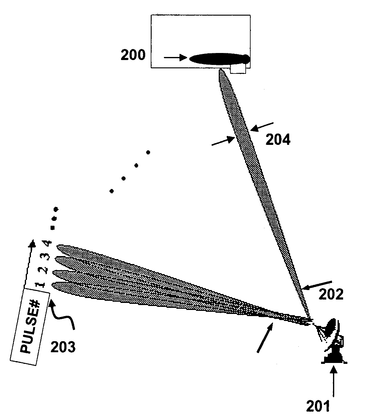
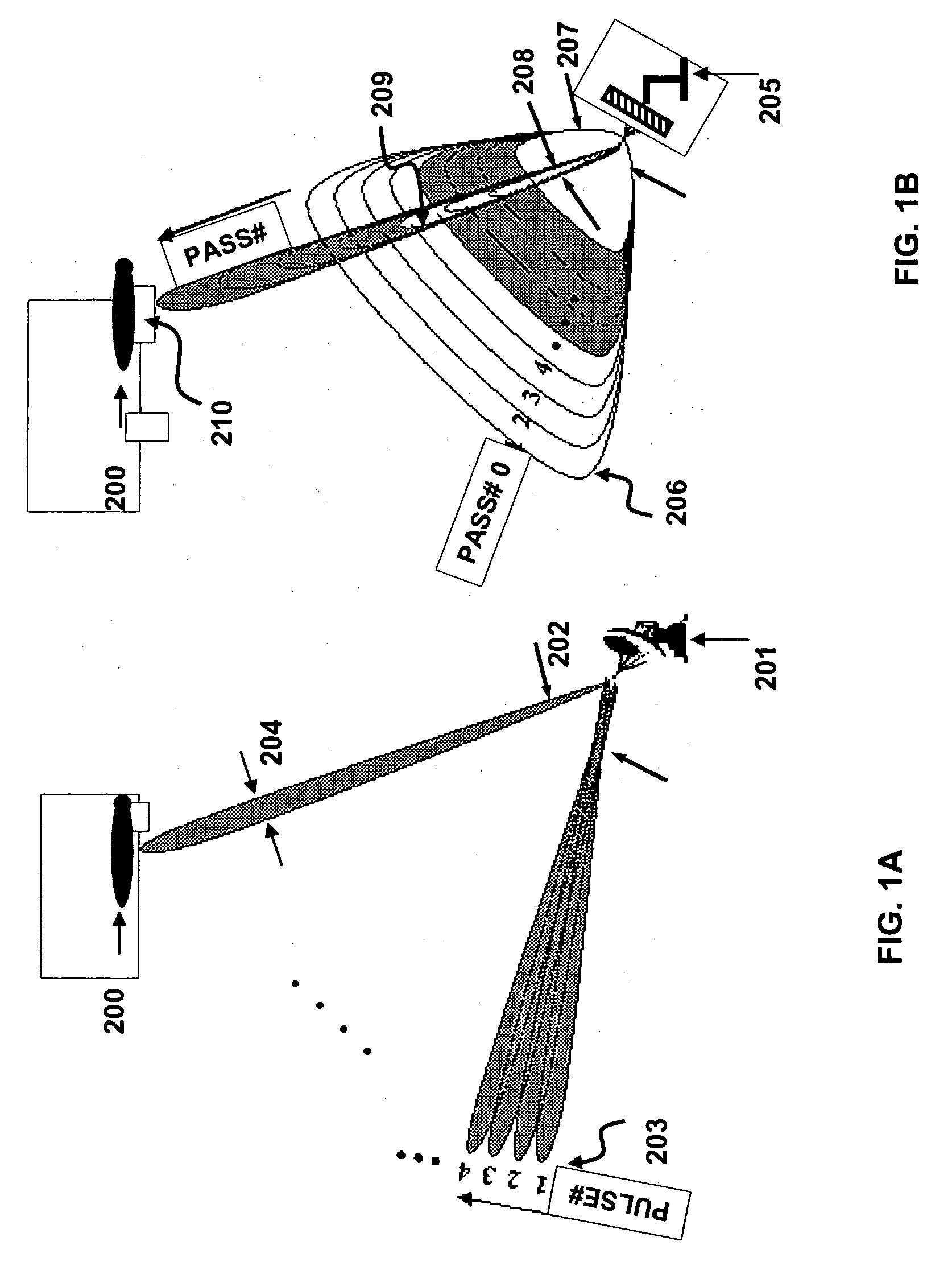
[0034] An example of a retrodirective noise-correlating (RNC) radar may be functionally explained in comparison to a conventional, pencil-beam search radar as shown in FIG. 1A. To find a target 200, a pencil-beam radar 201 must scan across a solid angle of space, ΩS 202 either electro...


PUM


Abstract

Embodiments of the present invention provide retrodirective noise-correlating radar that include: (1) a transmit antenna array that quiescently transmits random noise; (2) a receive antenna array, in a desired spatial relationship with the transmit antenna array, for collecting the reflected noise from a target; and (3) RF electronic components interconnecting antenna-element pairs between the receive and transmit arrays. In one group of embodiments, the radar automatically transforms the broad pattern from each element of the array (when transmitting or receiving random noise), to a narrow pattern characteristic of the entire array. In a second group of embodiments, a presence of a target and its range are determined quickly by a quasi-coherent build-up of signal in the time or frequency domains. In third group of embodiments a target angle and velocity vector are determined by cross correlation between two or more electronic channels connecting the transmit and receive arrays.

Description

RELATED APPLICATIONS [0001] This application claims benefit to U.S. Provisional Patent Application No. 60 / 538,979 filed on Jan. 26, 2004 which is incorporated herein by reference as if set forth in full herein.US GOVERNMENT RIGHTS [0002] A portion of the inventions disclosed and potentially claimed herein were made with Government support under Contract Number MDA972-03-C-0099. The Government has certain rights. Not all inventions disclosed herein were developed or conceived with government funding and it is not intended that the government attain rights in such inventions.FIELD OF THE INVENTION [0003] The present invention relates generally to electromagnetic radiation transmission and detection methods and apparatus, and more particularly to radar methods and apparatus that use retrodirective antennae configurations. Particular embodiments provide radar methods and apparatus employing quiescent noise transmission with noise-correlative signal processing. BACKGROUND OF THE INVENTIO...

Claims


Application Information

Patent Timeline
IPC IPC(8): G01S13/72
CPCG01S13/32G01S13/424G01S13/589H01Q3/2647G01S13/726G01S2013/0254G01S13/72
Inventor BROWN, ELLIOTT R.
Owner PHYSICAL DOMAINS
Why Eureka
Try Eureka