Locking device for heat dissipating device

a technology of locking device and heat sink, which is applied in the direction of snap fasteners, light and heating apparatus, buckles, etc., can solve the problems of difficult detachment of push-pins b>300/b> from the printed circuit board b>500, inability of heat sink b>200/b> to intimately contact with the cpu, and inability to detach push-pins b>300/b> from

Inactive Publication Date: 2005-09-15
HON HAI PRECISION IND CO LTD
View PDF9 Cites 9 Cited by
  • Summary
  • Abstract
  • Description
  • Claims
  • Application Information

AI Technical Summary

Benefits of technology

[0005] Accordingly, an object of the present invention is to provide a locking device which can firmly mount a heat sink to an electronic component and conveniently detach the heat sink from the electronic component.

Problems solved by technology

However, in disassembly, it is difficult to detach the push-pins 300 from the printed circuit board 500.
Furthermore, the springs 400 are prone to fatigue after a long time using.
As a result, the heat sink 200 is not capable of intimately contacting with the CPU 600.

Method used


Image

  • Locking device for heat dissipating device
  • Locking device for heat dissipating device
  • Locking device for heat dissipating device

Examples


Embodiment Construction

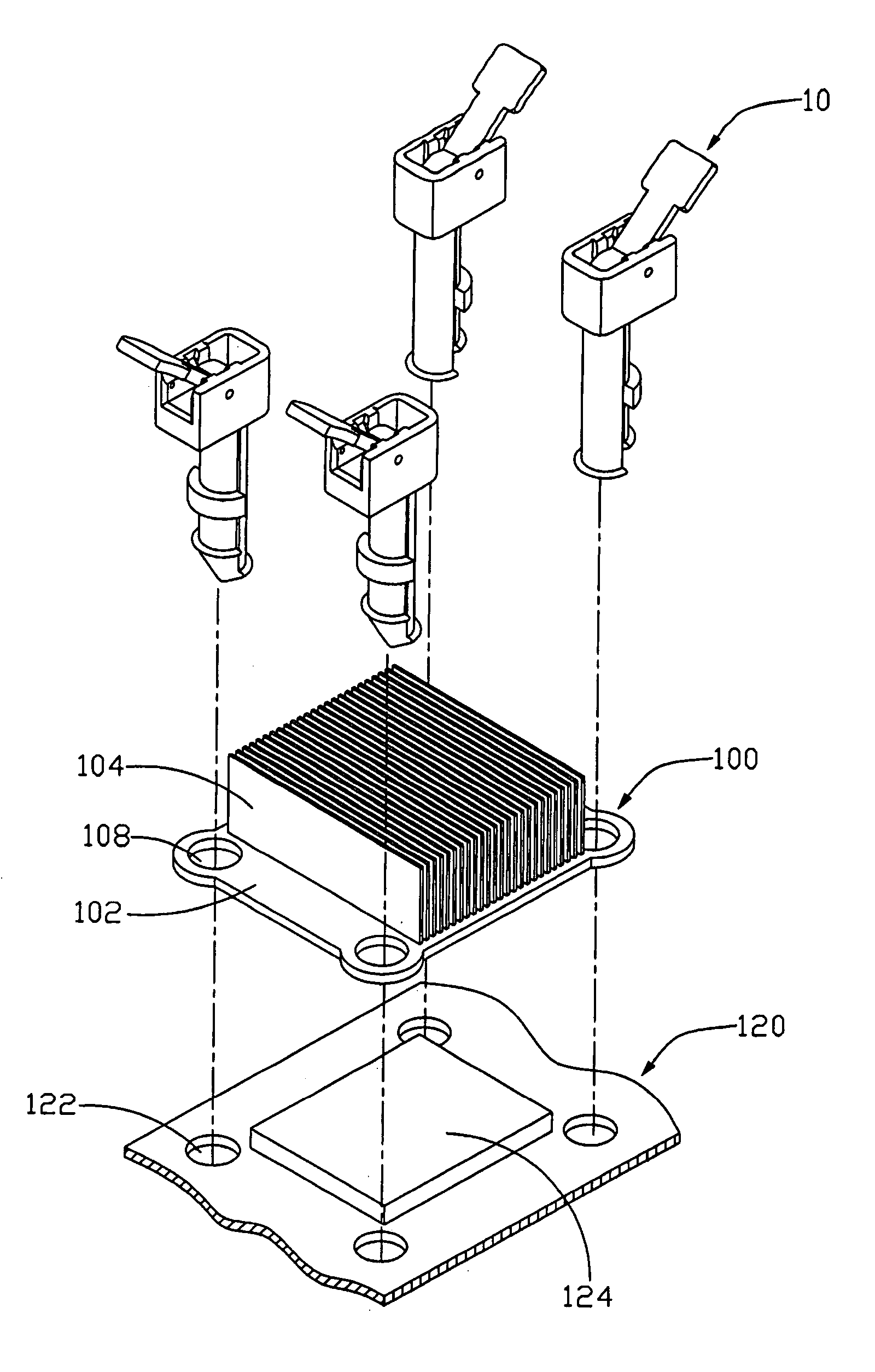
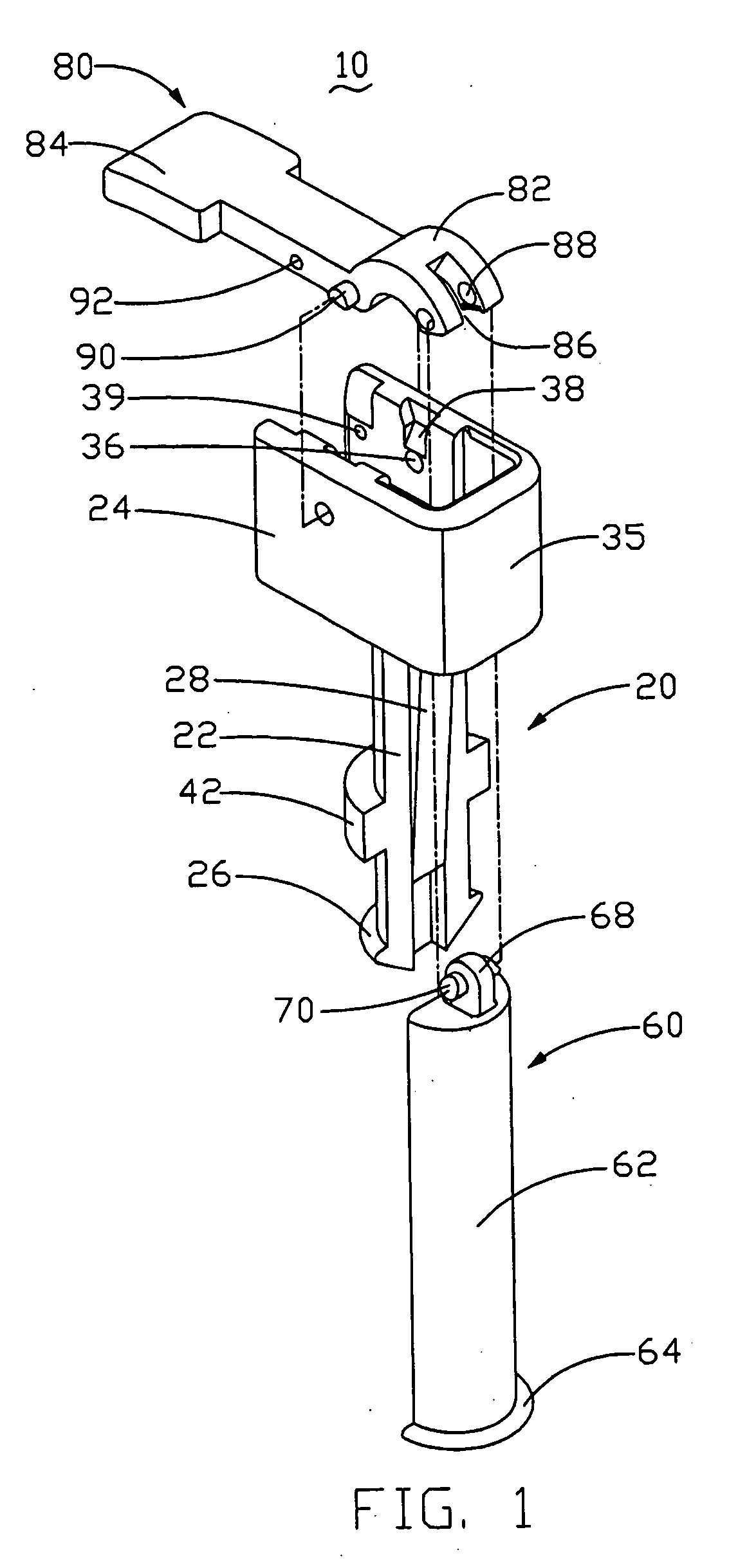
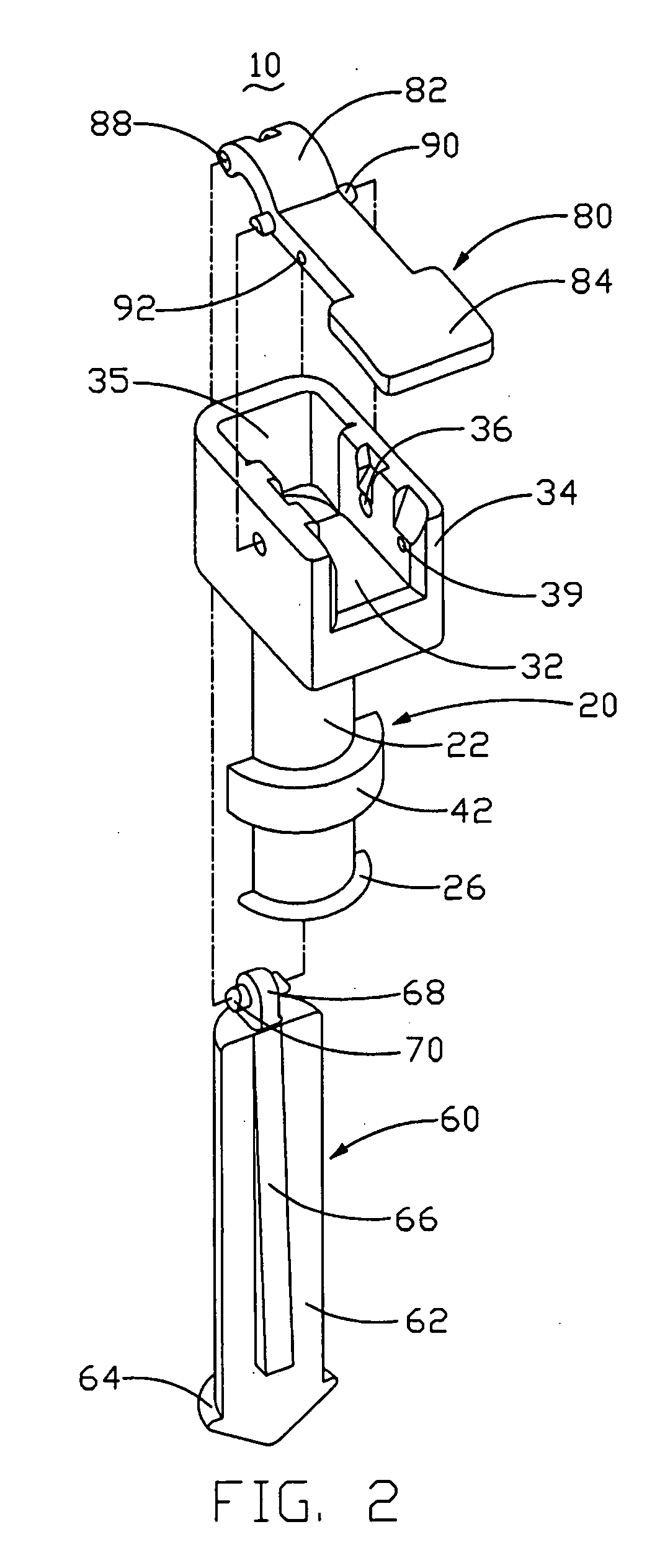
[0016]FIGS. 1-2 show a locking device 10 in accordance with a preferred embodiment of the present invention for mounting a heat sink 100 to a printed circuit board 120 (see FIG. 3).

[0017] The locking device 10 comprises a first locking member 20, a second locking member 60 and an operating member 80.

[0018] The first locking member 20 comprises a semi-cylindrical body 22, a head 24, a first hook 26 formed at the bottom of the body 22. The body 22 comprises a vertical planar face and a vertical circumferential face. A first wedge-shaped bar 28 is formed on the planar face of the body 22 in a longitudinal direction of the body 22. The thickness of the wedge-shaped bar 28 increases gradually from the first hook 26 to the head 24. A pressing block 42 is formed on the circumferential face of the body 22 adjacent to the first hook 26 so as to form a restriction mechanism. The head 24 comprises a bottom wall 32, a pair of side walls 34, and a connection wall 35 perpendicular to the bottom...


PUM


Abstract

A locking device for mounting a heat sink to a CPU mounted on a printed circuit board, includes a first locking member extending the heat sink and the circuit board and having a block for pressing the heat sink, an operating member pivotably connected to the first locking member, a second locking member extending the heat sink and the circuit board and pivotably connected to the operating member, and an actuating structure formed between the first and second locking members. The first and second locking members each includes a hook located below the circuit board. The operating member is pivotable about the first locking member to drive the second locking member to move upwardly and to cause the actuating structure to simultaneously drive the first and second locking members to move away from each other, whereby the hooks engage below the circuit board.

Description

TECHNICAL FIELD [0001] The present invention relates to a locking device, and particularly to a locking device which can conveniently mount a heat sink to an electronic component. BACKGROUND [0002] As computer technology continues to advance, electronic components such as central processing units (CPUs) of computers are made to provide faster operational speed and greater functional capabilities, which results in the CPU and other electronic components generating more and more heat. To ensure the CPU and other electronic components in the enclosure to function within their normal operating temperature ranges it is desirable to dissipate the generated heat quickly, for example, by using a heat sink attached to the CPU in the enclosure. Generally, a locking device is required for mounting the heat sink to the CPU and other electronic components. [0003]FIG. 8 shows a conventional locking device for mounting a heat sink 200 to a CPU 600. The CPU 600 is mounted on a printed circiut board...

Claims


Application Information

Patent Timeline
Patent Type & Authority Applications(United States)
IPC IPC(8): H01L23/32H05K7/20
CPCH01L23/4093H01L2924/0002Y10T24/44026Y10T24/42H01L2924/00
Inventor CHEN, CHUN-CHIZHOU, SHI-WENLEE, HSIEH-KUN
Owner HON HAI PRECISION IND CO LTD
Why Eureka
Try Eureka