Long-lasting self-lubricating large oil barrel

a self-lubricating, oil barrel technology, applied in the direction of bearings, shafts and bearings, bearings, etc., can solve the problems of insufficient lubricating effect of line sliding tracks and roller screws, inconvenience for industrialists and users, obstructed operations, etc., to achieve the effect of quick installation and replacemen

Inactive Publication Date: 2005-09-15
ABBA LINEAR TECH
View PDF8 Cites 23 Cited by
  • Summary
  • Abstract
  • Description
  • Claims
  • Application Information

AI Technical Summary

Benefits of technology

[0011] Referring to FIGS. 1 and 2, the invention comprises a sliding track 1, a sliding housing 2 and an oil storage tank 4.
[0012] The oil storage tank 4 is consisted of locating columns 24, 25, 26, 27 and 28, oil piths 33 and 34, and weight members 31 and 32.
[0013] The sliding track 2 is disposed with an adjacent connecting housing 3, which has a plurality of locating holes 7, 8, 9, 10 and 11 for accommodating the locating columns 24, 25, 26, 27 and 28 projecting at one side of the oil storage tank 4 as shown in FIG. 2, thereby readily installing and replacing the oil storage tank 4 during application as shown in FIGS. 3 and 4. The locating holes 7, 8, 9, 10 and 11 are respectively provided with grooves 12, 13, 14, 15 and 16 at inner peripheries thereof. The locating columns 24, 25, 26, 27 and 28 are provided with ribs 17, 18, 19, 20 and 21 at outer peripheries thereof. Thus, the oil storage tank 4 is firmly positioned by fastening the grooves 12, 13, 14, 15 and 16 with the ribs 17, 18, 19, 20 and 21. The oil storage tank 4 further has a storage chamber at an interior thereof for accommodating the oil piths 33 and 34, the weight members 31 and 32, and a lubricating oil. The locating columns 27 and 25 are respectively disposed with through openings 5 and 6 for inserting oil supply ends 22 and 23 of the oil piths 33 and 34. When the oil supply ends 22 and 23 come into contact with an oil-containing sponge 35, using capillarity of the oil piths 33 and 34, the lubricating oil in the oil storage tank 4 is evenly absorbed and distributed within the oil-containing sponge. The oil-containing sponge 35 is displaced at the sliding track 1, and thus the lubricating oil is proportionally applied to the sliding track 1, thereby accomplishing long-lasting and smooth lubricating effects when a roller 45 is rolled at the sliding track 1.
[0014] Ends 29 and 30 of the oil piths 33 and 34 are respectively inserted with the weight members 31 and 32. Using weight of the weight members 31 and 32, the ends 29 and 30 of the oil piths 33 and 34 are maintained at lowest positions in the oil storage tank 4 as shown in FIGS. 5, 6 and 7, thereby enabling the oil storage tank 4 to supply the lubricating oil according to different installation directions of the sliding housing 2 and the sliding track 1 to achieve thorough lubricating effects.

Problems solved by technology

However, the lubricant added is only capable of maintaining temporary lubricating effects, meaning that it is essential that the lubricant be constantly added to make the lubricating effects last.
This is a common shortcoming that causes industrialists and users inconveniences.
In addition, the periodical manual oil supply frequently leads to insufficient lubricating effects of the line sliding tracks and roller screws.
As a result, mechanical parts are prone to wear to cause obstructed operations yet adding another shortcoming.
Above all, when a user supplies a lubricating oil, the lubricating oil is likely to ooze out of an oil opening for that the oil opening is too small.
A machine base may thus become contaminated by the oil, and product quality may even be further undesirably affected.

Method used


Image

  • Long-lasting self-lubricating large oil barrel
  • Long-lasting self-lubricating large oil barrel
  • Long-lasting self-lubricating large oil barrel

Examples


Embodiment Construction

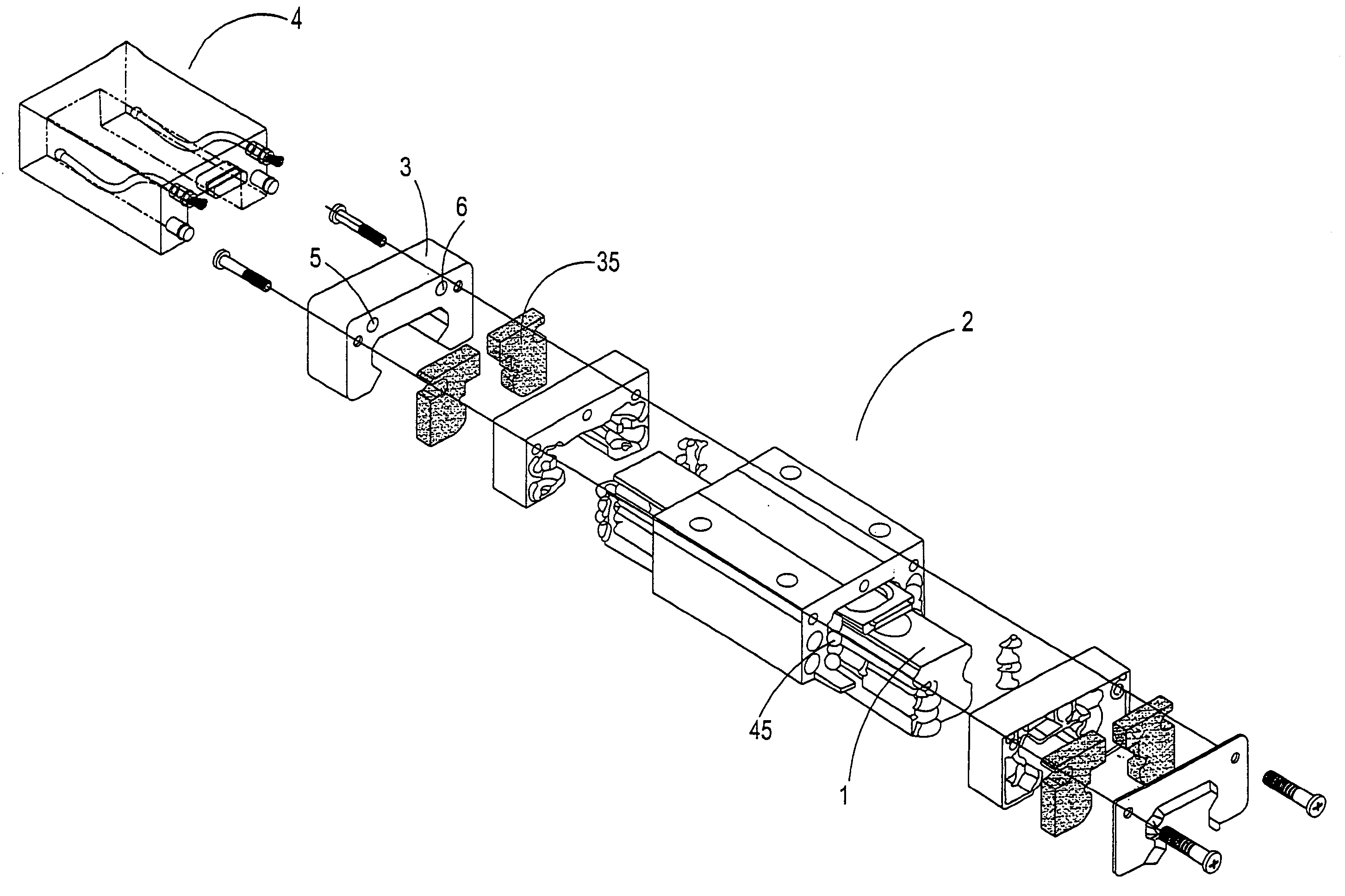
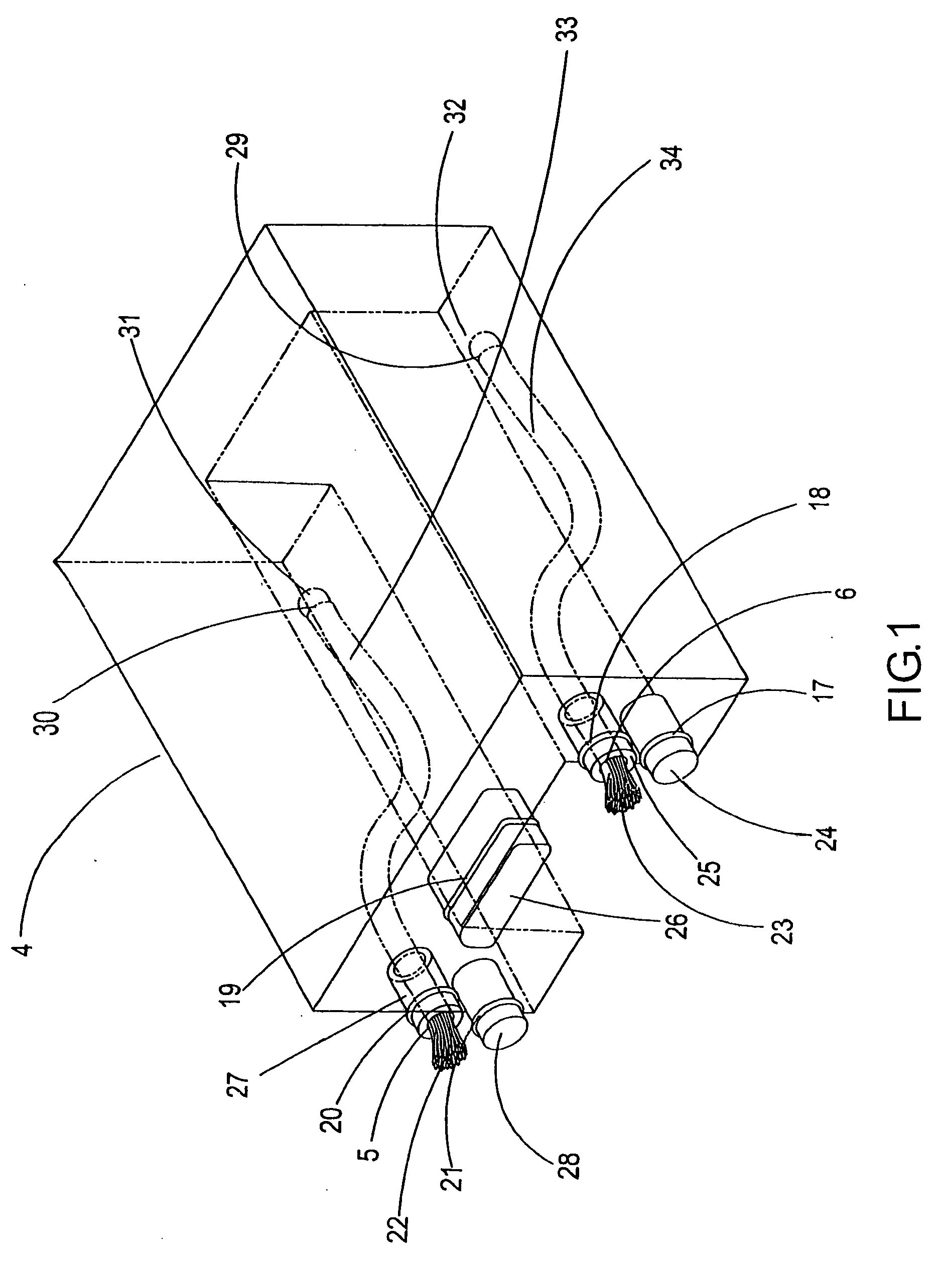
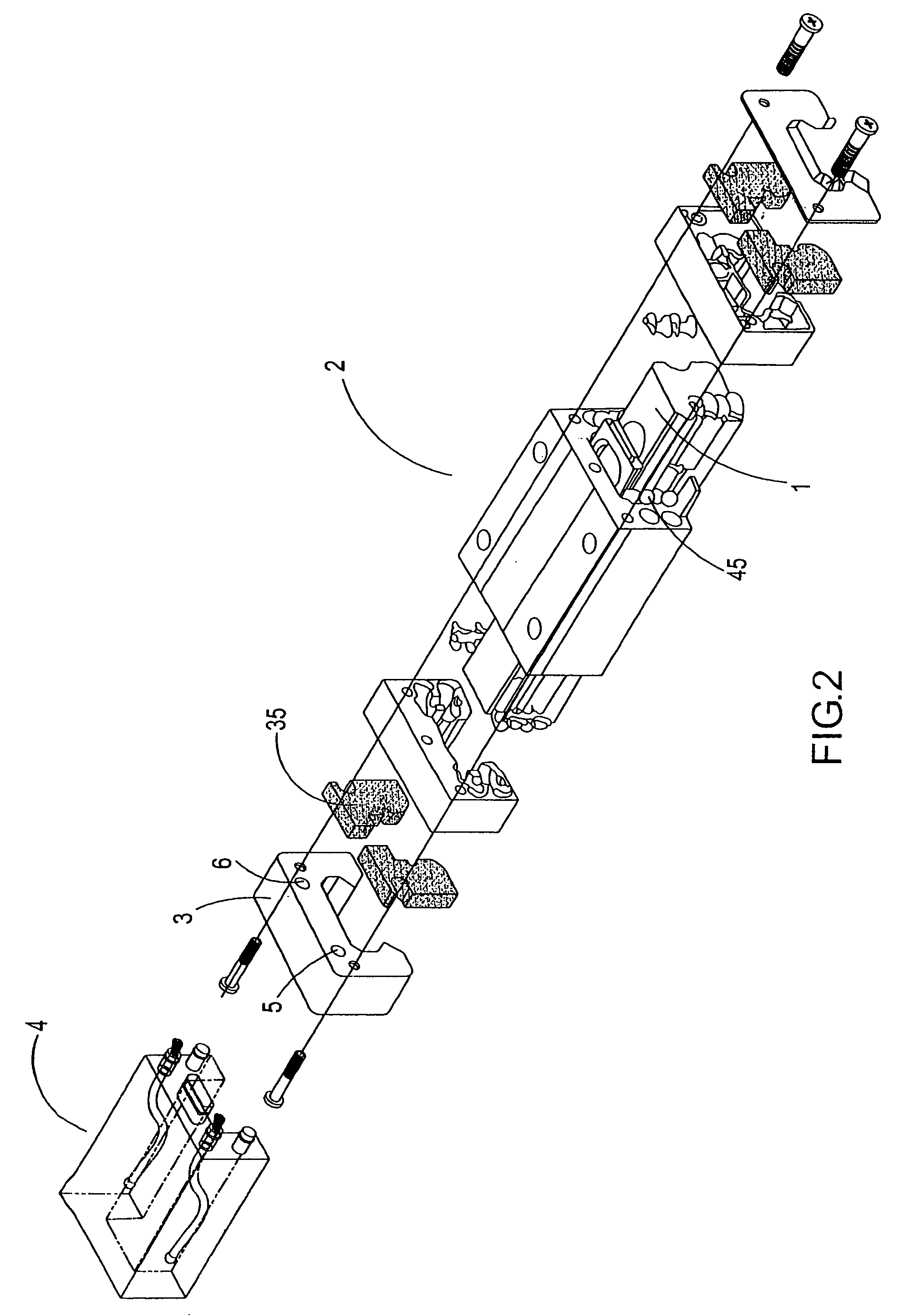
[0026] To put the long-lasting self-lubricating large oil barrel according to the invention to use, the oil storage tank 4 is fastened at the sliding track 2, and the oil piths 33 and 34 then come into contact with an oil-containing sponge 35. Using capillarity of the oil piths 33 and 34, the lubricating oil in the oil storage tank 4 is absorbed and distributed within the oil-containing sponge 35. The oil-containing sponge 35 is displaced at the sliding track 1, and thus the lubricating oil is proportionally applied to the sliding track 1, thereby accomplishing long-lasting and smooth lubricating effects when a roller 45 is rolled at the sliding track 1 and lengthening usage lifespan of the sliding housing 2 and the sliding track 1.

[0027] Furthermore, with reference to FIG. 8, according to the invention, a screw bolt 46 may be utilized penetrate through the oil storage tank 4 to be adjusted and fixed at the sliding housing 2. Similarly, quick installation and positioning effects ar...


PUM


Abstract

A long-lasting self-lubricating large oil barrel includes a sliding a sliding track, a sliding housing and an oil storage tank. The oil storage tank has oil piths, and weight members a lubricating oil at an interior thereof. Using capillarity of the oil piths, the lubricating oil is evenly absorbed and distributed within an oil-containing sponge. With displacement of the oil-containing sponge at the sliding track, the lubricating oil is proportionally applied to the sliding track, thereby accomplishing long-lasting and smooth lubricating effects when a roller is rolled at the sliding track. Using weight of the weight members, the ends of the oil piths are maintained at lowest positions of in the oil storage tank, thereby enabling the oil storage tank to supply the lubricating oil according to different installation directions of the sliding housing and the sliding track to achieve thorough lubricating effects.

Description

BACKGROUND OF THE INVENTION [0001] (a) Field of the Invention [0002] The invention relates to a long-lasting self-lubricating large oil barrel, and more particularly, to a long-lasting self-lubricating large oil barrel that comprises an oil storage tank having oil piths therein in contact with an oil-containing sponge of a sliding housing thereof. Using capillarity of the oil piths, a lubricating oil in the oil storage tank is evenly absorbed and distributed within the oil-containing sponge. With displacement of the oil-containing sponge at the sliding track, the lubricating oil is proportionally applied to the sliding track, thereby accomplishing long-lasting and smooth lubricating effects when a roller is rolled at the sliding track. [0003] (b) Description of the Prior Art [0004] Mechanics are the parentage of industry. As mechanical industries advance, parts such as line sliding tracks and roller screws are extensively utilized by various processing and transmission apparatuses. ...

Claims


Application Information

Patent Timeline
Patent Type & Authority Applications(United States)
IPC IPC(8): F16N9/04F16C29/06F16C29/08F16C33/10F16C33/66F16N7/12F16N19/00
CPCF16C33/6637F16C29/0642
Inventor LEE, MAO-TULEE, HSUN-CHENSHUN, CHUNG-YUAN
Owner ABBA LINEAR TECH
Why Eureka
Try Eureka