
Apparatus and method for cleaning an image transfer device

a technology of image transfer device and apparatus, which is applied in the direction of electrographic process apparatus, instruments, optics, etc., can solve the problems of reducing the print quality of subsequently printed images, affecting the useful life of the photoconductor surface, and affecting the transfer effect of developed images

Active Publication Date: 2005-09-15
HEWLETT PACKARD DEV CO LP
View PDF17 Cites 26 Cited by
  • Summary
  • Abstract
  • Description
  • Claims
  • Application Information

AI Technical Summary

Benefits of technology

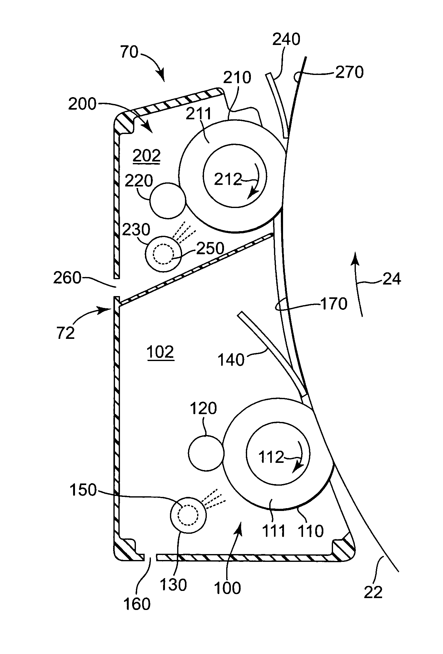
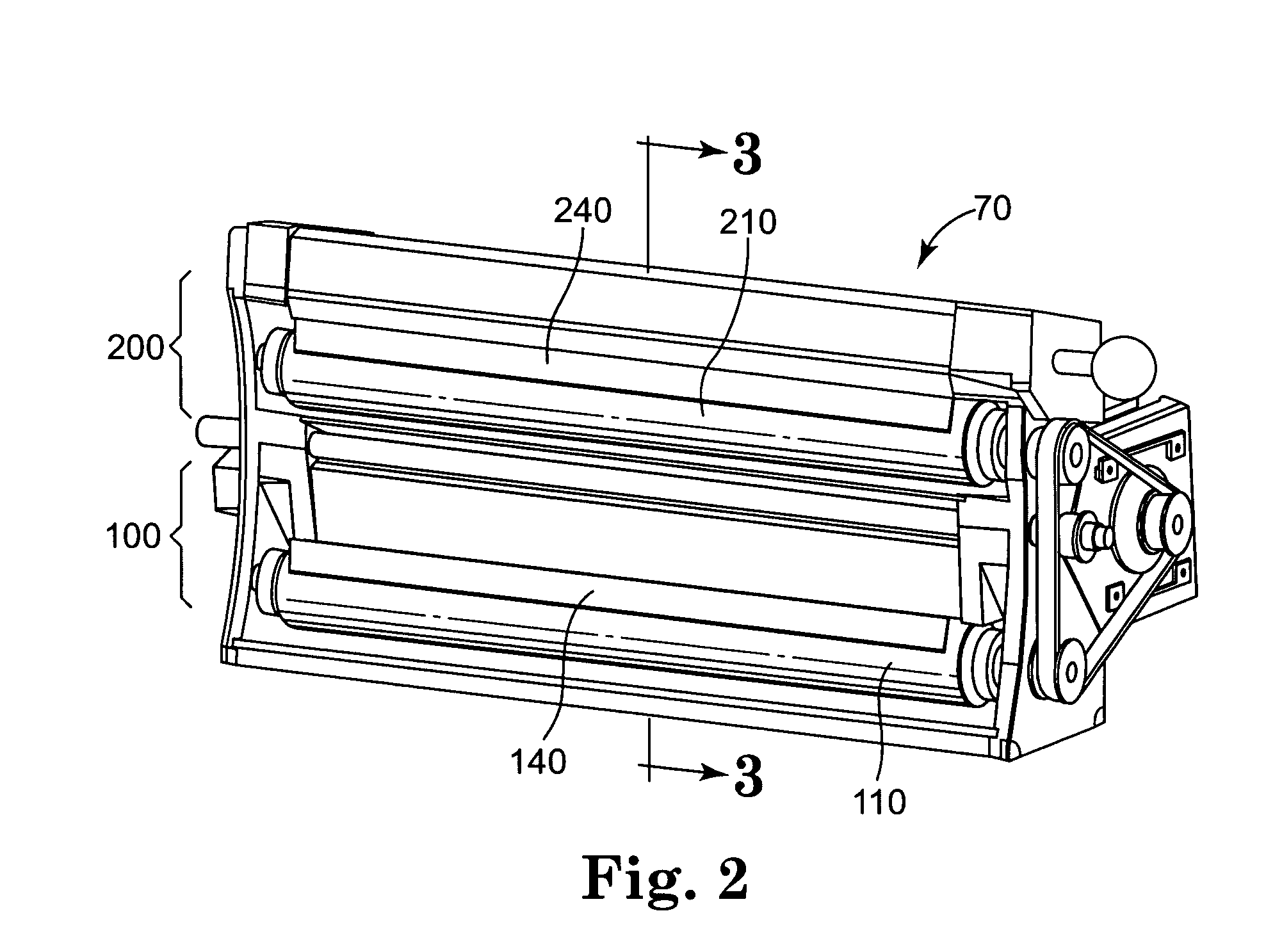
The invention is about a device and method for cleaning an image transfer surface. It includes two cleaning stations that apply cleaning fluid and remove residual material from the surface. The first cleaning station uses a tank to supply cleaning fluid and receives residual material from the first cleaning station. The second cleaning station uses a tank to supply cleaning fluid and receives residual material from the second cleaning station. The second tank is also connected to the first tank and supplies cleaning fluid to it. The technical effect of this invention is to provide a more efficient and effective way to clean image transfer surfaces in image transfer devices.

Problems solved by technology

However, in an actual printing process, some of the developed image may not be completely transferred, leaving residual materials such as toner, imaging oil, charge directors and other dissolved materials on the photoconductor surface.
The residual materials on the photoconductor surface reduce the print quality of subsequently printed images and shorten the useful life of the photoconductor surface.
Although the described cleaning method does clean much of the residual material from the photoconductor surface, a layer of dirty imaging oil remains on the photoconductor surface.
The print quality of the printer is thus adversely affected and the life of the photoconductor is shortened.

Method used


Image

  • Apparatus and method for cleaning an image transfer device
  • Apparatus and method for cleaning an image transfer device
  • Apparatus and method for cleaning an image transfer device

Examples


example

[0028] A LEP printer having a cleaning apparatus 70 as described above was operated for 45,000 printing cycles. The change in contamination of the imaging oil in the first tank 82 and second tank 84 is illustrated in the graph of FIG. 5. Contamination of the imaging oil is represented by the oil conductivity, as charge director concentration is proportional to the oil conductivity. After completion of 45,000 printing cycles, the second tank 84 had a conductivity of 3 pmho / cm, as illustrated by line 300, while the first tank 82 had a conductivity of 55 pmho / cm, as illustrated by line 302. Over the course of 45,000 printing cycles, the LEP printer consumed 6 liters of imaging oil from the first tank 82. The imaging oil used from the first tank 82 was replaced with the 3 pmho / cm oil from the second tank 84, while the 3 pmho / cm oil in the second tank 84 was replaced with 0 pmho / cm oil.

[0029] As described herein, the liquid electrophotograpic printer with the cleaning apparatus 70 accor...


PUM


Abstract

An apparatus and method for cleaning an image transfer surface in an image transfer device. The cleaning apparatus includes a first cleaning station and a second cleaning station positioned to consecutively clean the image transfer surface. The first and second cleaning stations apply cleaning fluid to the image transfer surface and remove cleaning fluid with residual material from the image transfer surface. A first tank supplies cleaning fluid to, and receives cleaning fluid with residual material from, the first cleaning station. A second tank supplies cleaning fluid to, and receives cleaning fluid with residual material from, the second cleaning station. The second tank also supplies cleaning fluid to the first tank.

Description

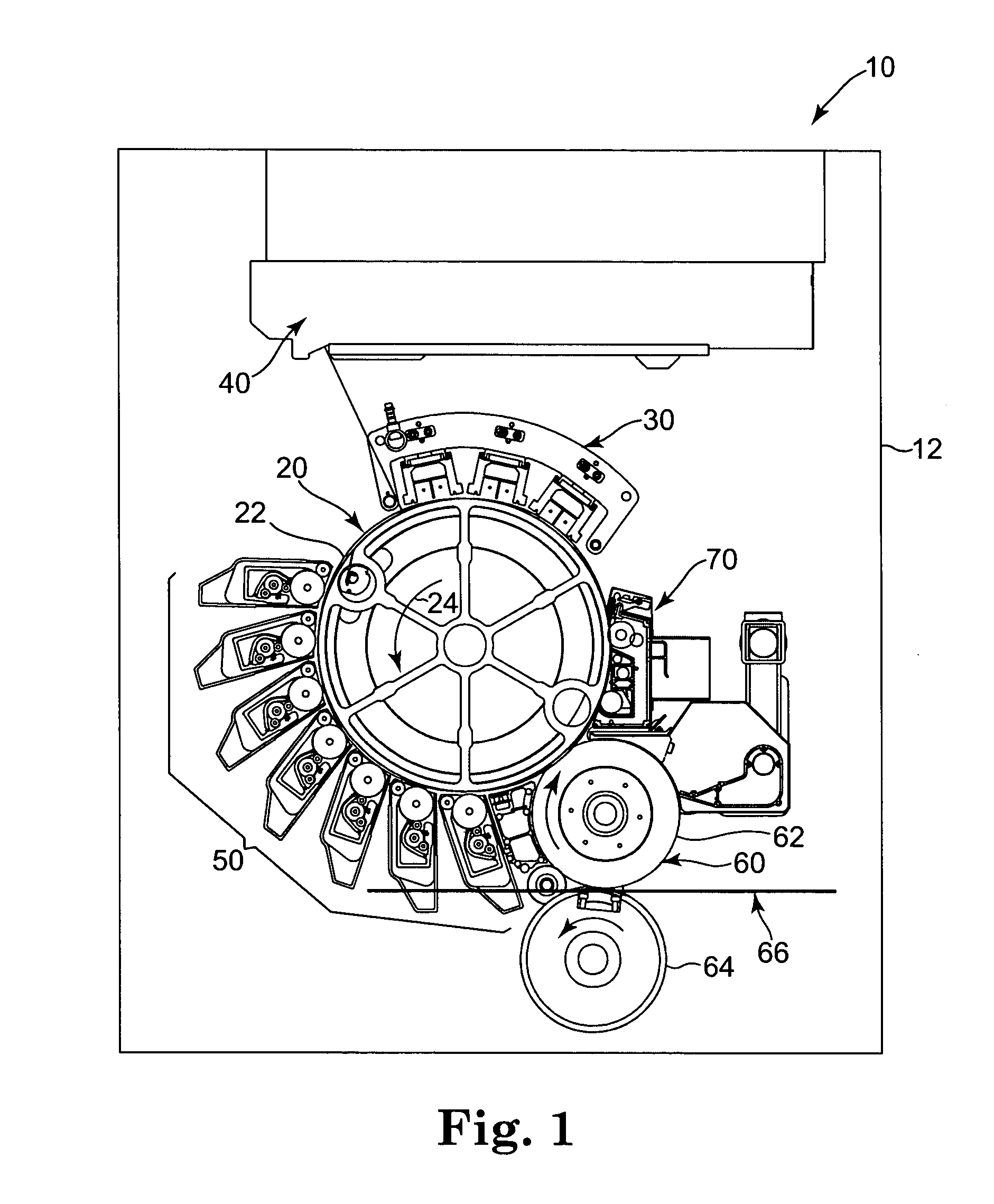
BACKGROUND OF THE INVENTION [0001] The present invention generally relates to image transfer technology and, more particularly, to an apparatus and method for removing contaminants from photoconducting surfaces of liquid electrophotographic printing components after printing, and a liquid electrophotographic printer having the cleaning apparatus. [0002] As used herein, the term “printer” generally refers to all types of devices used for creating and / or transferring an image in a liquid electrophotographic process, including laser printers, copiers, facsimiles, and the like. [0003] In a liquid electrophotographic (LEP) printer, an electrostatic latent image is created on the surface of an insulating, photoconducting material by selectively exposing areas of the photoconducting surface to light (such as a laser). A difference in electrostatic charge density is created between the areas on the photoconducting surface exposed and unexposed to light. The electrostatic latent image is dev...

Claims


Application Information

Patent Timeline
Patent Type & Authority Applications(United States)
IPC IPC(8): G03G15/16G03G21/00
CPCG03G21/0088G03G15/161
Inventor GILA, OMERLEE, MICHAEL H.
Owner HEWLETT PACKARD DEV CO LP
Learn More