
Radially crush-resistant stent

a stent and radial elasticity technology, applied in the field of biomedical stents and valves, can solve the problems of insufficient radial elasticity and easy radial crush of stents

Inactive Publication Date: 2005-09-15
MEDTRONIC VASCULAR INC
View PDF14 Cites 368 Cited by
  • Summary
  • Abstract
  • Description
  • Claims
  • Application Information

AI Technical Summary

Problems solved by technology

Stents are susceptible to radial crush and insufficient radial elasticity.

Method used


Image

  • Radially crush-resistant stent
  • Radially crush-resistant stent
  • Radially crush-resistant stent

Examples


Embodiment Construction

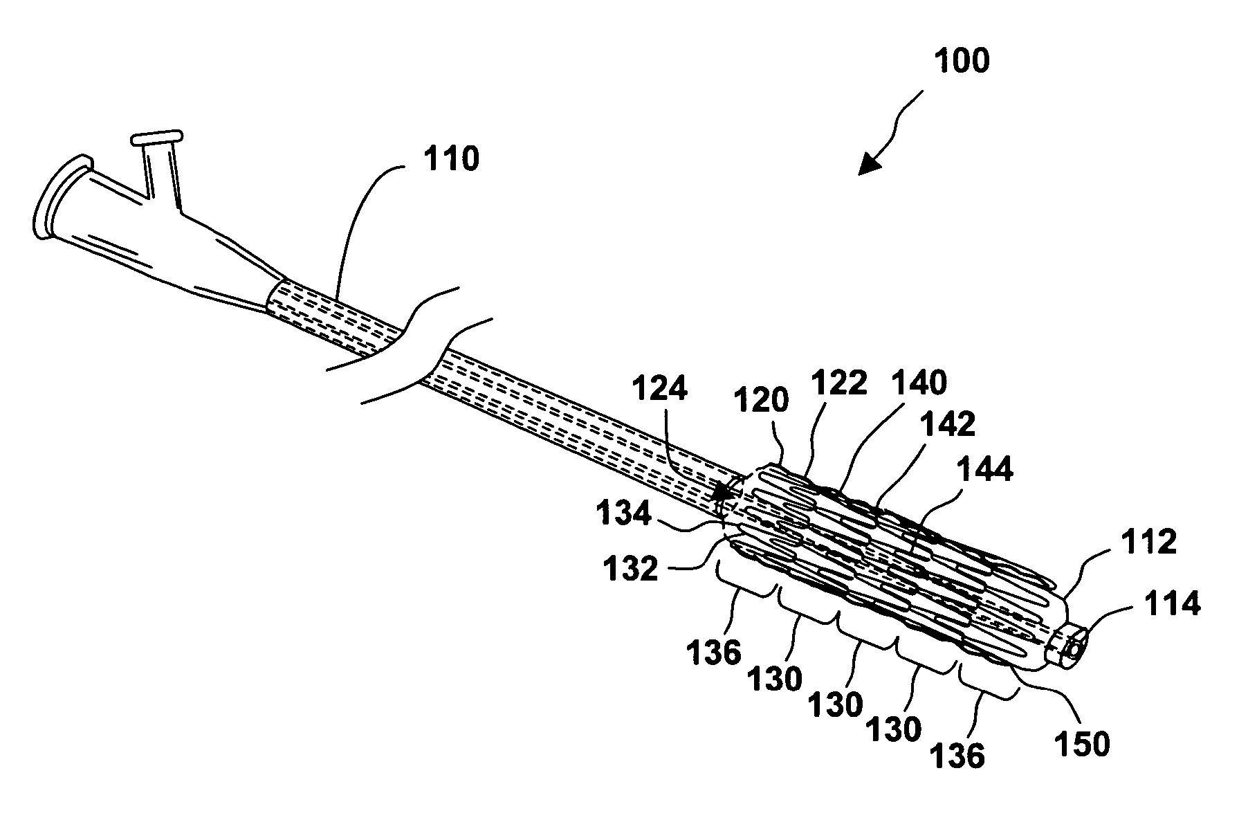
[0023]FIG. 1 illustrates a system for treating a vascular condition, in accordance with one embodiment of the present invention. Vascular condition treatment system 100 includes a catheter 110 and a stent 120 coupled to catheter 110. Stent 120 includes a stent framework 122 having at least one stent segment 130 with a plurality of interconnected struts 132 and crowns 134 and at least one stiffening ring 140 having a plurality of ring segments 142 connected between circumferentially adjacent crowns 134 of stent segment 130. Stent segments 130 are sinusoidally shaped, continuously formed in a loop or ring with smooth, rounded corners referred to as crowns 134 at each bend, and substantially straight segments in between crowns 134 referred to as struts 132. In one example, struts 132 and crowns 134 have a nominally uniform length and radius, respectively.

[0024] In one example, expandable stent 120 is configured to support a vascular lumen. Stent 120 is comprised of multiple stent segm...


PUM


Abstract

A system for treating a vascular condition includes a catheter and a stent coupled to the catheter. The stent includes a stent framework having at least one stent segment with a plurality of interconnected struts and crowns and at least one stiffening ring having a plurality of ring segments connected between circumferentially adjacent crowns of the stent segment. The stiffening ring is oriented circumferentially about a longitudinal axis of the stent framework when the stent is deployed. A stent and a method of treating a vascular condition are also disclosed.

Description

RELATED APPLICATIONS [0001] This application claims the benefit of U.S. Provisional Patent Application 60 / 553,208 filed Mar. 15, 2004.FIELD OF THE INVENTION [0002] This invention relates generally to biomedical stents and valves. More specifically, the invention relates to a stent having an adapted stent framework to increase radial stiffness, reduce radial crush, reduce deployment recoil, and minimize overexpansion, while minimizing length changes during expansion. BACKGROUND OF THE INVENTION [0003] Biomedical stents may be implanted and deployed within the human body to reinforce blood vessels or other vessels as part of surgical procedures for enlarging and stabilizing body lumens, or to support bioprosthetic valves implanted within the circulatory system. With generally open tubular structures of metallic or polymeric material, endovascular stents typically have apertured or lattice-like walls, and can be either balloon expandable or self-expanding. A stent is usually deployed b...

Claims


Application Information

Patent Timeline
IPC IPC(8): A61F2/00A61F2/06A61F2/24A61F2/84A61F2/90
CPCA61F2/2418A61F2/91A61F2/915A61F2/958A61F2230/0054A61F2002/91533A61F2002/91558A61F2250/0018A61F2002/91525
Inventor DOLAN, MARK JEFFREY
Owner MEDTRONIC VASCULAR INC
Features
  • Generate Ideas
  • Intellectual Property
  • Life Sciences
  • Materials
  • Tech Scout
  • Unparalleled Data Quality
  • Higher Quality Content
  • 60% Fewer Hallucinations
Learn More