Modular knee prosthesis

a knee prosthesis and module technology, applied in the field of implantable articles, can solve the problems of uncoupling of mobile bearing and rotating platform design, adversely affecting the goal of satisfactorily restoring clinical biomechanics and function of the joint,

Inactive Publication Date: 2005-09-15
OMNILIFE SCI INC
View PDF98 Cites 25 Cited by
  • Summary
  • Abstract
  • Description
  • Claims
  • Application Information

AI Technical Summary

Benefits of technology

[0008] It is an aspect of the present general inventive concept to provide a component designed to allow for tibial component articular surfa

Problems solved by technology

Improper placement or orientation of one or more components of the device or an improper fit to the patient's anatomy can adversely affect the goal of satisfactorily restoring the clinical biomechanics and function of the joint.
The primary difference between the fixed bearing designs and the mobile bearing and rotating platform designs is that the mobile bearing and rotating platform designs uncouple, to some de

Method used


Image

  • Modular knee prosthesis
  • Modular knee prosthesis
  • Modular knee prosthesis

Examples


Embodiment Construction

[0021] Reference will now be made in detail to the presently preferred embodiments of the inventive concept, examples of which are illustrated in the accompanying drawings, wherein like reference numerals refer to like elements throughout.

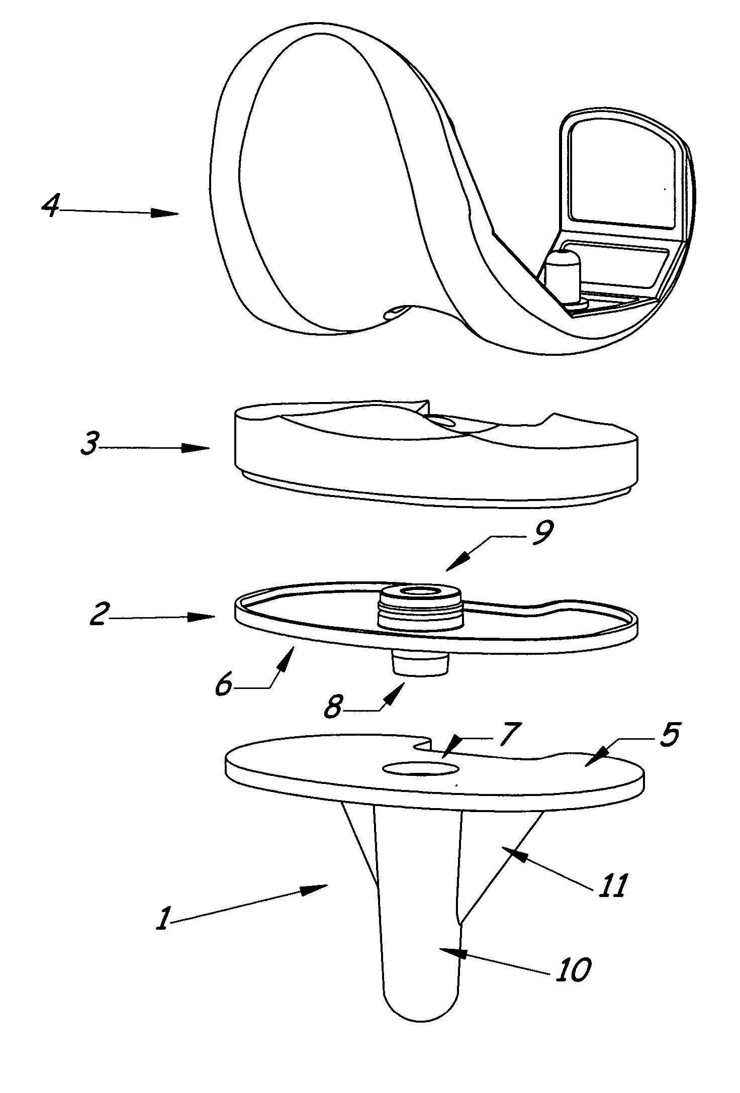
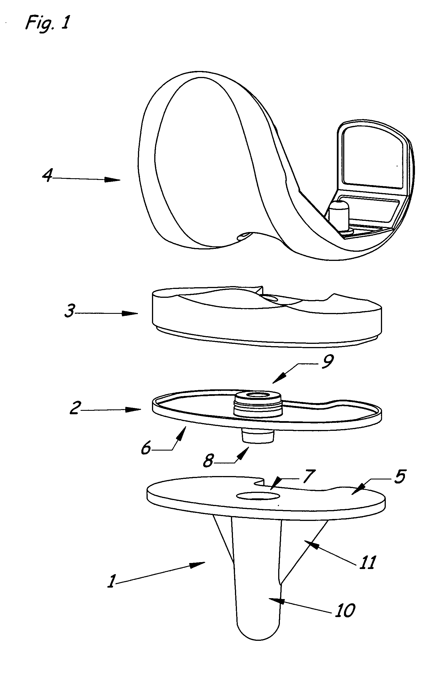
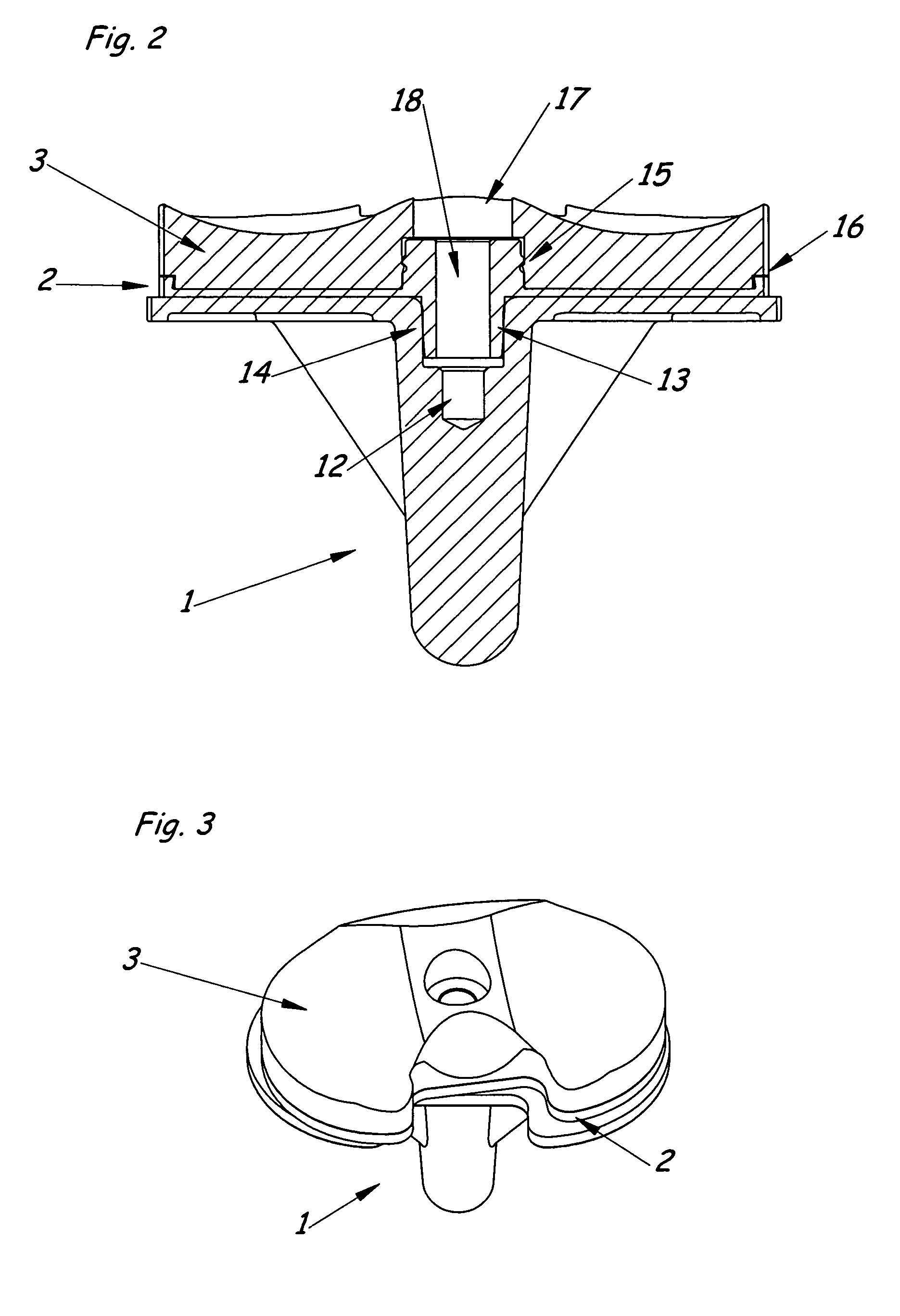
[0022] The present inventive concept is related to the tibial component of a knee replacement prosthesis for both cemented and cementless applications; however the inventive concept is also applicable to other implantable prostheses such as ankles, fingers, and elbows, all of which may include a tray portion for resurfacing one or both sides of a joint. The present inventive concept is particularly advantageous in allowing optimal sizing and placement for use in an artificial knee and as such this description will reference a knee prosthesis.

[0023] The components that comprise these devices are designed such that assembly of the components can be accomplished either before implantation, such as on the back table during surgery, or, alternatively ...


PUM


Abstract

A joint prosthesis having in part a tray that is supported by metaphyseal bone, such as the tibial component of a knee prosthesis. The tibial tray and tibial bearing portions can be de-coupled, resulting in two or more distinct pieces

Description

[0001] The present application claims benefit of provisional application No. 60 / 547,627, which is incorporated by reference herein in its entirety.BACKGROUND OF THE INVENTION [0002] 1. Field of the Invention [0003] The present i relates generally to an implantable article that is particularly suitable for use as an artificial joint prosthesis and more particularly to a prosthesis having in part a tray that is supported by metaphyseal bone, such as the tibial component of a knee prosthesis. [0004] 2. Description of the Related Art [0005] Artificial knee joint prostheses are widely used today, restoring mobility to patients affected by a variety of conditions, particularly arthritis. The satisfactory performance of these devices can be affected not only by the design of the prosthesis itself, but also by the final placement and spatial orientation of the implanted components both individually and together in combination. Improper placement or orientation of one or more components of t...

Claims


Application Information

Patent Timeline
IPC IPC(8): A61F2/38
CPCA61F2/3868A61F2/389A61F2002/30332A61F2002/30884A61F2002/30492A61F2002/305A61F2002/30604A61F2002/30364
Inventor CIPOLLETTI, GEORGECHEAL, EDWARD
Owner OMNILIFE SCI INC
Why Eureka
Try Eureka