Software development using visual interfaces

a visual interface and software development technology, applied in the direction of source code creation/generation, specific program execution arrangements, program control, etc., can solve the problems of reducing the practical applicability of diagrams and pictures in software engineering, not being adequately addressed, and users not seeing a progression

Active Publication Date: 2005-09-15
RAMCO SYSTEMS
View PDF16 Cites 28 Cited by
  • Summary
  • Abstract
  • Description
  • Claims
  • Application Information

AI Technical Summary

Problems solved by technology

Some outstanding issues that may not be adequately addressed include: (1) the diagrammatic conventions bear little or no resemblance to the look and feel of the eventual software delivered; (2) users do not see a progression in realizing functioning software through what will be delivered to them; and (3) software professionals have to visualize and specify the expected behavior using different conventions.
These outstanding issues, and others, have historically reduced the practical applicability of diagrams and pictures in software engineering.
These do not enforce any translation semantics when the high level specifications are used during different stages of a software development life cycle (SDLC).
This leads to a high degree of information leakage at different stages of the software lifecycle development process.
Such information leakage results in the development of an application that is not in tune with the high level requirements that were envisaged in the initial stages of the development.
This results in costly rework, both in terms of cost and schedule, at later stages of the SDLC.

Method used


Image

  • Software development using visual interfaces
  • Software development using visual interfaces
  • Software development using visual interfaces

Examples


Embodiment Construction

[0022] In the following detailed description of the preferred embodiments, reference is made to the accompanying drawings that form a part hereof, and in which are shown by way of illustration specific embodiments in which the invention may be practiced. It is understood that other embodiments may be utilized and structural changes may be made without departing from the scope of the present invention.

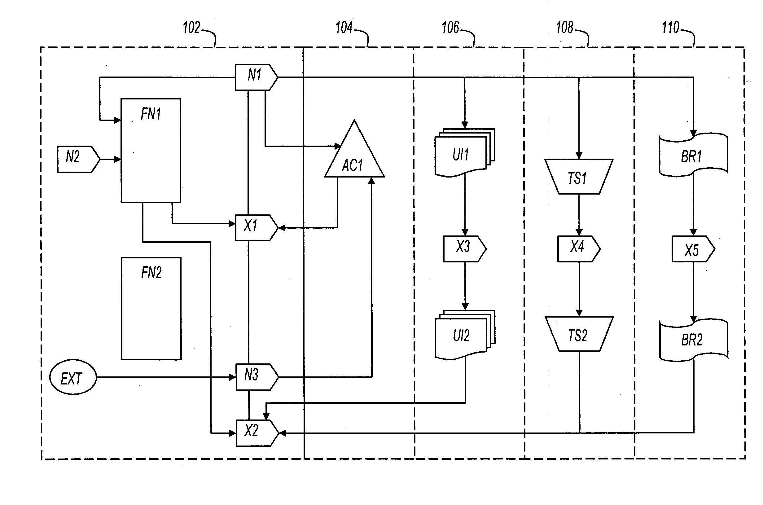
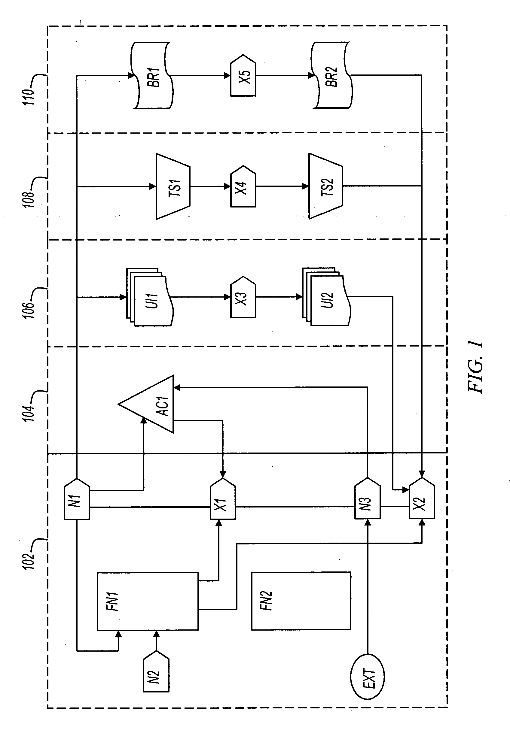
[0023] Enterprise applications are systems that typically respond to either external stimulus or a system stimulus. To capture stimulus and stimulus response, various embodiments of the present invention model business systems using node / event pairs. Within each node / event pair, the event depicts the stimulus, the node depicts the response to the stimulus, and the response to the stimulus may lead to a new stimulus to the business system. The use of events and nodes to specify the behavior of the business systems at different levels ensures that there is coherence between the specifica...


PUM


Abstract

User interfaces created for software systems are used as the basis for gathering and/or disseminating requirements, behavioral specifications, review processes, and documentation. A computer readable medium is described, the medium having computer executable instruction to cause a system perform the method.

Description

RELATED APPLICATIONS [0001] Benefit is claimed under 35 U.S.C. 119(e) to U.S. Provisional Application Ser. No. 60 / 553,087, entitled “Approach for representing business architecture for information systems” by Sundararajan et al., filed Mar. 15, 2004, which is herein incorporated in its entirety by reference for all purposes. [0002] Benefit is also claimed under 35 U.S.C. 119(e) to U.S. Provisional Application Ser. No. 60 / 553,256, “Approach for representing technical architecture” by Sundararajan et al., filed Mar. 15, 2004, which is incorporated herein by reference for all purposes. [0003] Benefit is also claimed under 35 U.S.C. 119(e) to U.S. Provisional Application Ser. No. 60 / 553,352, “Mapping business and technical architecture elements to implementation technologies” by Sundararajan et al., filed Mar. 15, 2004, which is incorporated herein by reference for all purposes. [0004] Benefit is also claimed under 35 U.S.C. 119(e) to U.S. Provisional Application Ser. No. 60 / 553,470, “S...

Claims


Application Information

Patent Timeline
Patent Type & Authority Applications(United States)
IPC IPC(8): G06F9/44
CPCG06F8/34G06F8/10
Inventor SUNDARARAJAN, PARTHASARATHYMEENAKSHISUNDARAM, KRISHNAMOORTHYRAMASWAMY, SRINIVASANDEVALLA, RAGHURAMGOPALSAMY, KANNAPPANNATARAJAN, KRISHNANSEETHARAMAN, SUBRAMANIANJAYARAMAN, SHYAMALARAMARATNAM, VENKATASUBRAMANIAN
Owner RAMCO SYSTEMS
Why Eureka
Try Eureka