
Systems and methods of performing stateful signaling transactions in a distributed processing environment

Active Publication Date: 2005-09-15
TEKELEC GLOBAL INC
View PDF38 Cites 66 Cited by
  • Summary
  • Abstract
  • Description
  • Claims
  • Application Information

AI Technical Summary

Benefits of technology

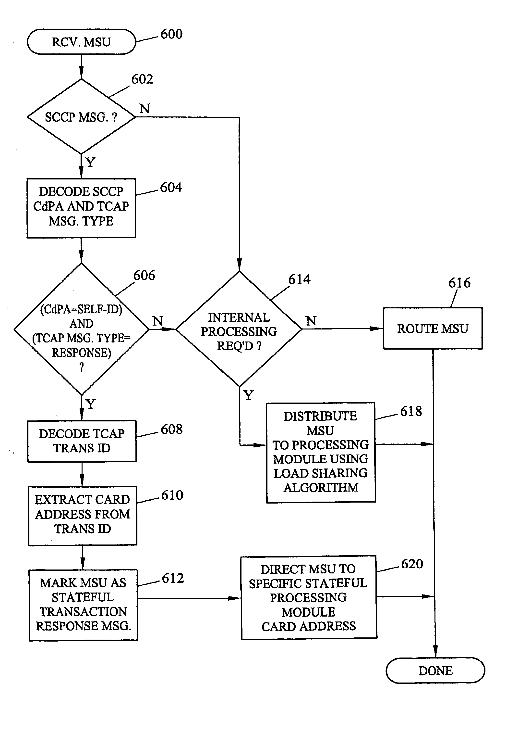
[0011] Using processing module identifiers to distribute messages enables rapid and accurate location of the processing module that originates a stateful transaction. In addition, combining load sharing with stateful transaction processing provides increased versatility over conventional STPs that performed only stateless processing, such as GTT.
[0014] Because the STP load shares each end-office-originated query message among multiple stateful processing modules, stateful processing is efficiently and reliably performed by the STP. In addition, because the STP inserts a stateful processing module identifier in STP-originated query messages in a manner that will cause the recipient to include the stateful processing module identifier in the corresponding response message, the STP ensures correct distribution of stateful transaction response messages.

Problems solved by technology

Such stateful transactions may include related messages that are received or transmitted by the signal transfer point at different times. One problem with implementing stateful transactions in a distributed processing environment is that load sharing algorithms will not always guarantee that subsequent signaling messages in a stateful transaction are processed by the same processing module as the signaling messages that initiated the stateful transaction.
While such a solution would ensure the proper distribution of messages for stateful transactions, the reliability of such a system is decreased over systems with distributed SCCP processing.

Method used


Image

  • Systems and methods of performing stateful signaling transactions in a distributed processing environment
  • Systems and methods of performing stateful signaling transactions in a distributed processing environment
  • Systems and methods of performing stateful signaling transactions in a distributed processing environment

Examples


Embodiment Construction

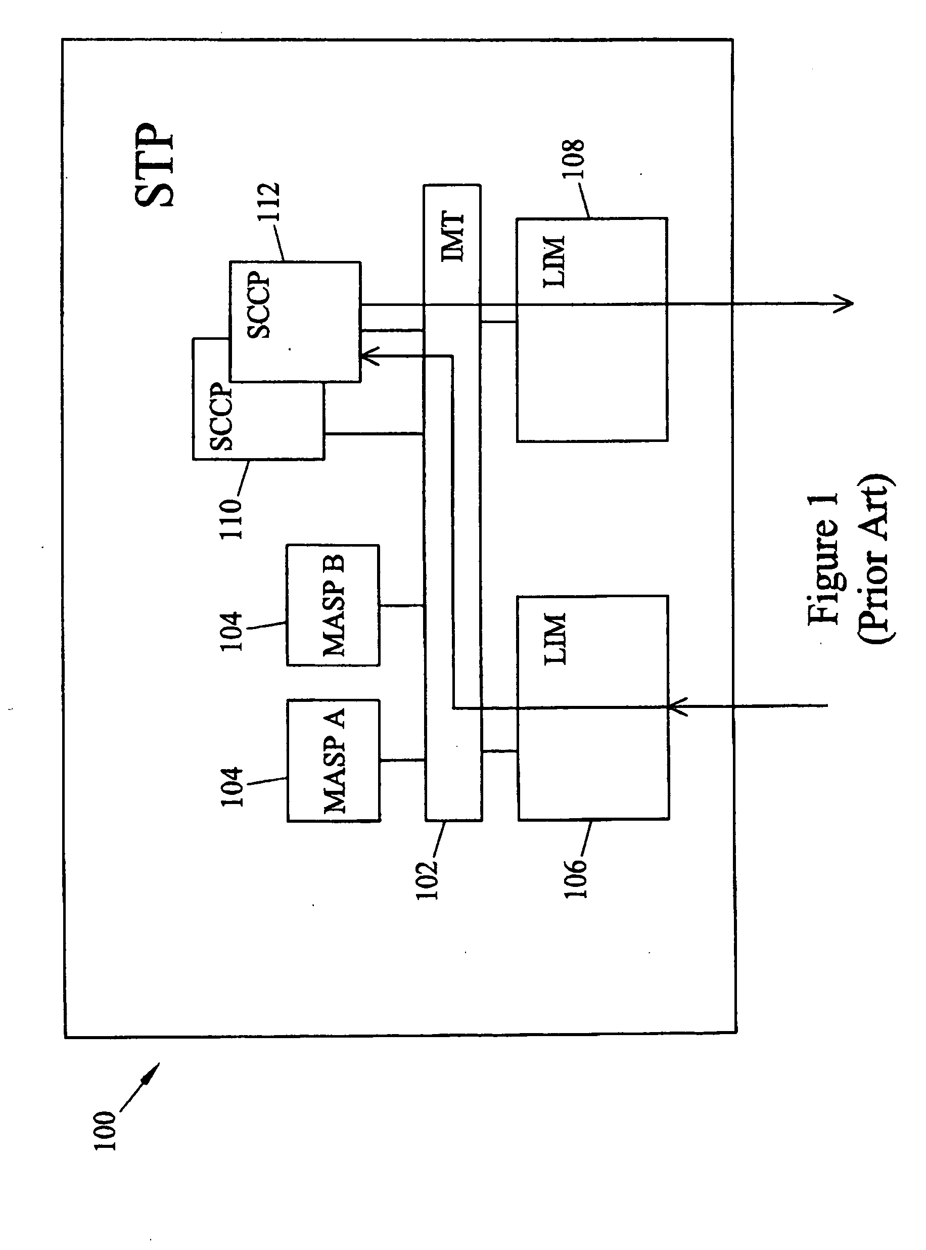
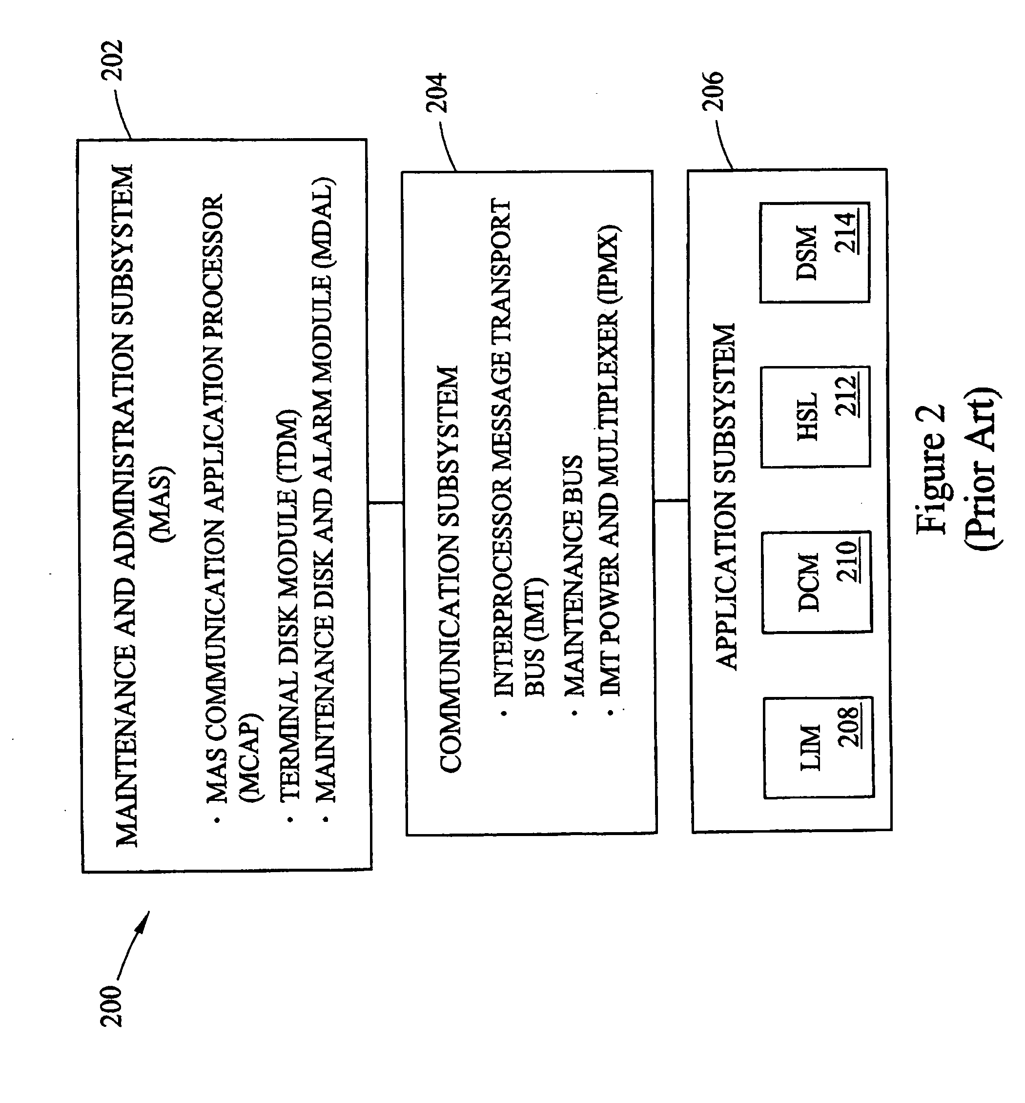
[0036] According to one embodiment, the present invention includes a communications network routing node, such as an STP configured to perform stateful signaling transactions and load sharing. FIG. 2 is a block diagram illustrating an exemplary STP 200 suitable for use with embodiments of the present invention. Referring to FIG. 2, STP 200 includes the following subsystems: a maintenance and administration subsystem (MAS) 202, a communication subsystem 204 and an application subsystem 206. MAS 202 provides maintenance communications, initial program loading, peripheral services, alarm processing and system disks. Communication subsystem 204 includes an interprocessor message transport (IMT) bus that is the main communication bus among all subsystems in STP 200. The IMT bus may include 1 Gbps counter-rotating serial rings.

[0037] Application subsystem 206 includes application cards or printed circuit boards capable of communicating with the other cards through the IMT bus. Numerous t...


PUM


Abstract

Methods and systems for performing stateful signaling transactions in a distributed processing environment are disclosed. A method for performing stateful signaling transactions in a distributed processing environment includes receiving a signaling message at a routing node, such as a signal transfer point. The signaling message is distributed to one of the plurality of stateful processing modules. The receiving stateful processing module buffers the signaling message and initiates a stateful transaction based on the signaling message. Initiating the stateful transaction may include generating a query message and inserting a stateful processing module identifier in the query message. The query message is sent to an external node, such as an SCP, which formulates a response. The SCP may insert the stateful processing module in the response and send the response back to the signal transfer point. The signal transfer point decodes the response and uses the stateful processing module identifier to forward the response to the correct stateful processing module.

Description

TECHNICAL FIELD [0001] The present invention relates to methods and systems for performing stateful signaling transactions. More particularly, the present invention relates to methods and systems for performing stateful signaling transactions in a distributed processing environment. BACKGROUND ART [0002] In telecommunications signaling networks, signaling message routing nodes often include distributed processing architectures. For example, signaling system 7 (SS7) signal transfer points (STPs) and SS7-over-Internet protocol (IP) gateways often include distributed processing architectures. Such architectures may include groups of circuit boards, each having one or more microprocessors, that perform stateless message processing functions, such as message routing. Dividing the processing to perform signaling message routing among multiple processors increases reliability over centralized routing architectures. [0003] In addition to message routing, STPs have been used to perform other...

Claims


Application Information

Patent Timeline
IPC IPC(8): G06F15/16
CPCH04Q3/0025
Inventor PALMER, JONATHAN JAMESERICKSON, MARK ALLENDAVIDSON, MARK ERNESTRAO, RAGHAVENDRA GOPALAAGARWAL, DEVESHMARSICO, PETER JOSEPH
Owner TEKELEC GLOBAL INC
Learn More