Self-supporting pleated filter and method of making same

a filter and self-supporting technology, applied in the field of self-supporting, pleated filtering, can solve the problems of limiting the application of this technique, increasing the cost, and affecting the stability of the filter media, and achieve the effect of easy media chang

Inactive Publication Date: 2005-09-22
3M INNOVATIVE PROPERTIES CO
View PDF44 Cites 45 Cited by
  • Summary
  • Abstract
  • Description
  • Claims
  • Application Information

AI Technical Summary

Benefits of technology

[0009] In one embodiment, the method of making the self-supporting pleated filter includes forming a plurality of pleats in a filter media that extend along a front face and a rear face. The pleats include a plurality of pleat tips and sloping side surfaces generally perpendicular to the direction of pleating. At least one reinforcing strip oriented in the direction of pleating is bonded to the pleat tips on the front face to form a pleated filter. At least one reinforcing member is positioned along the rear face of the filter media. The filter media is then cut to size. Frame members are optionally applied for some filtration applications. Alternatively, the self-supporting pleated filter can be used without a frame or inserted into a permanent frame that permits the media to be easily changed.

Problems solved by technology

The filter media can become unsteady when air pressure is applied to one side.
However, the glue beads require a large quantity of melt bonding agent, resulting in increased cost.
Additionally, the glue beads require the pleats to be closely spaced, limiting application of this technique to pleat counts generally greater than about six pleats per inch.
Thompson does not disclose automated filter element manufacturing.

Method used


Image

  • Self-supporting pleated filter and method of making same
  • Self-supporting pleated filter and method of making same
  • Self-supporting pleated filter and method of making same

Examples


Embodiment Construction

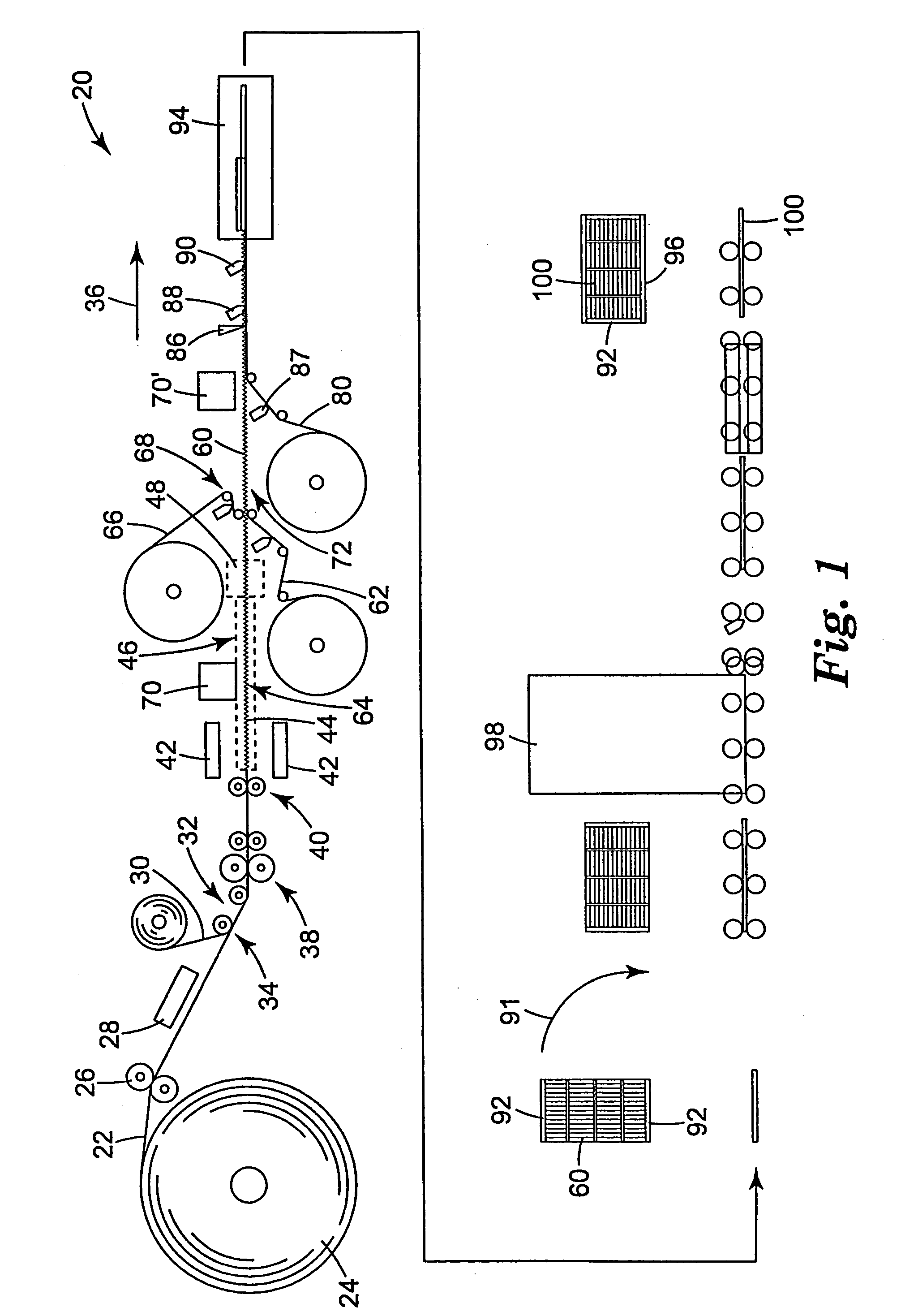
[0030]FIG. 1 is a schematic illustration of a system 20 for performing the method of the present invention. Filter media 22 is typically provided on a continuous roll 24. The media 22 may be slit to the desired width at slitting station 26. The media 22 may optionally be preheated at a heating station 28 to facilitate processing. In the illustrated embodiment, the heating station 28 is an infrared heater.

[0031] In one embodiment, a reinforcing member 30 is applied to a rear face 32 of the media 22 at a location 34. As will be discussed in detail below, the reinforcing member 30 may be applied as one or more continuous strips oriented in the direction of pleating 36, as discrete reinforcing members oriented perpendicular to the direction of pleating 36, or a variety of other configurations. The reinforcing member 30 may optionally be bonded to the media 22 using a variety of techniques, such as adhesive bonding, thermal bonding, solvent bonding, or ultrasonic bonding. In this embodi...


PUM

PropertyMeasurementUnit
widthaaaaaaaaaa
depthaaaaaaaaaa
depthaaaaaaaaaa

Abstract

A self-supporting, pleated filter, and method of making the same. The method includes forming a plurality of pleats in a filter media that extend along a front face and a rear face. The pleats include a plurality of pleat tips and sloping side surfaces generally perpendicular to the direction of pleating. At least one planar reinforcing strip oriented in the direction of pleating is bonded to the pleat tips on the front face. At least one reinforcing member is positioned along the rear face of the filter media. The filter media is then cut to size. Frame members are applied for some applications. The reinforcing member may be a reinforcing strip oriented in the direction of pleating and bonded to the rear face of the filter media prior to the step of forming the plurality of pleats. A second planar reinforcing strip may optionally be bonded to the reinforcing strip pleat tips. The reinforcing member, the first reinforcing strip and the second reinforcing strip can be aligned to form a truss structure. Alternatively, reinforcing strips oriented perpendicular to the direction of pleating are bonded to the rear face of the filter media prior to the step of forming the pleats. In another embodiment, a reinforcing member is applied to the rear face of the filter media after the pleats have been formed. The reinforcing member is positioned along at least one of the sloping side surfaces of the pleats on the rear face in a direction perpendicular to the direction of pleating. In another embodiment, a scrim is positioned along the rear face of the filter media. The scrim can be bonded to the frame members, the filter media and / or a portion of the frame members extend over a perimeter of the scrim to secure it to the pleated filter.

Description

TECHNICAL FIELD [0001] The present invention is directed to a method of making a self-supporting, pleated filter with reinforcing structures that resists pleat deformation, and in particular, to a fully automated method of making a pleated filter for air filtration. BACKGROUND OF THE INVENTION [0002] The surface area of filter media is a major factor in determining flow resistance (i.e., pressure drop) and loading capacity of a pleated filter. The surface area of a pleated filter media is determined by the size of the pleated filter, the depth of the pleats, and the pleat density. Since the external dimensions of pleated filters are often restricted by the particular application, the number of pleats per inch (pleat density) can be increased to improve filtration performance. [0003] The ability of air filter media to withstand operating pressures is typically dependent upon the pleat count, the pleat depth and the stiffness of the filter media. The filter media can become unsteady w...

Claims


Application Information

Patent Timeline
Patent Type & Authority Applications(United States)
IPC IPC(8): B01D46/00B01D46/10B01D46/52
CPCB01D46/0001B01D46/10B01D2265/06B01D2265/04B01D46/523
Inventor SUNDET, DOUGLAS C.PITZEN, JAMES F.
Owner 3M INNOVATIVE PROPERTIES CO
Why Eureka
Try Eureka