Monitoring refrigerant charge

a technology of refrigerant charge and monitoring device, which is applied in the direction of refrigeration safety arrangement, refrigeration machine, sorption machine, etc., can solve the problems of affecting the ability of the system to provide adequate cooling, damage to system components such as the compressor, and inadequate refrigerant amoun

Active Publication Date: 2005-09-22
CARRIER CORP
View PDF10 Cites 91 Cited by
  • Summary
  • Abstract
  • Description
  • Claims
  • Application Information

AI Technical Summary

Problems solved by technology

It is possible for the refrigerant charge in the system to be initially too low or for some refrigerant to be lost or reduced during operation to a level that hinders the ability of the system to provide adequate cooling.
At some levels, a loss of refrigerant charge may cause damage to the system components such as the compressor.
Typical causes of inadequate refrigerant amounts include inadequate charge at the factory or during installation in the field or leakage throug...

Method used


Image

  • Monitoring refrigerant charge
  • Monitoring refrigerant charge

Examples


Embodiment Construction

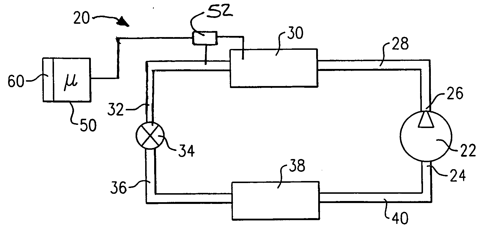
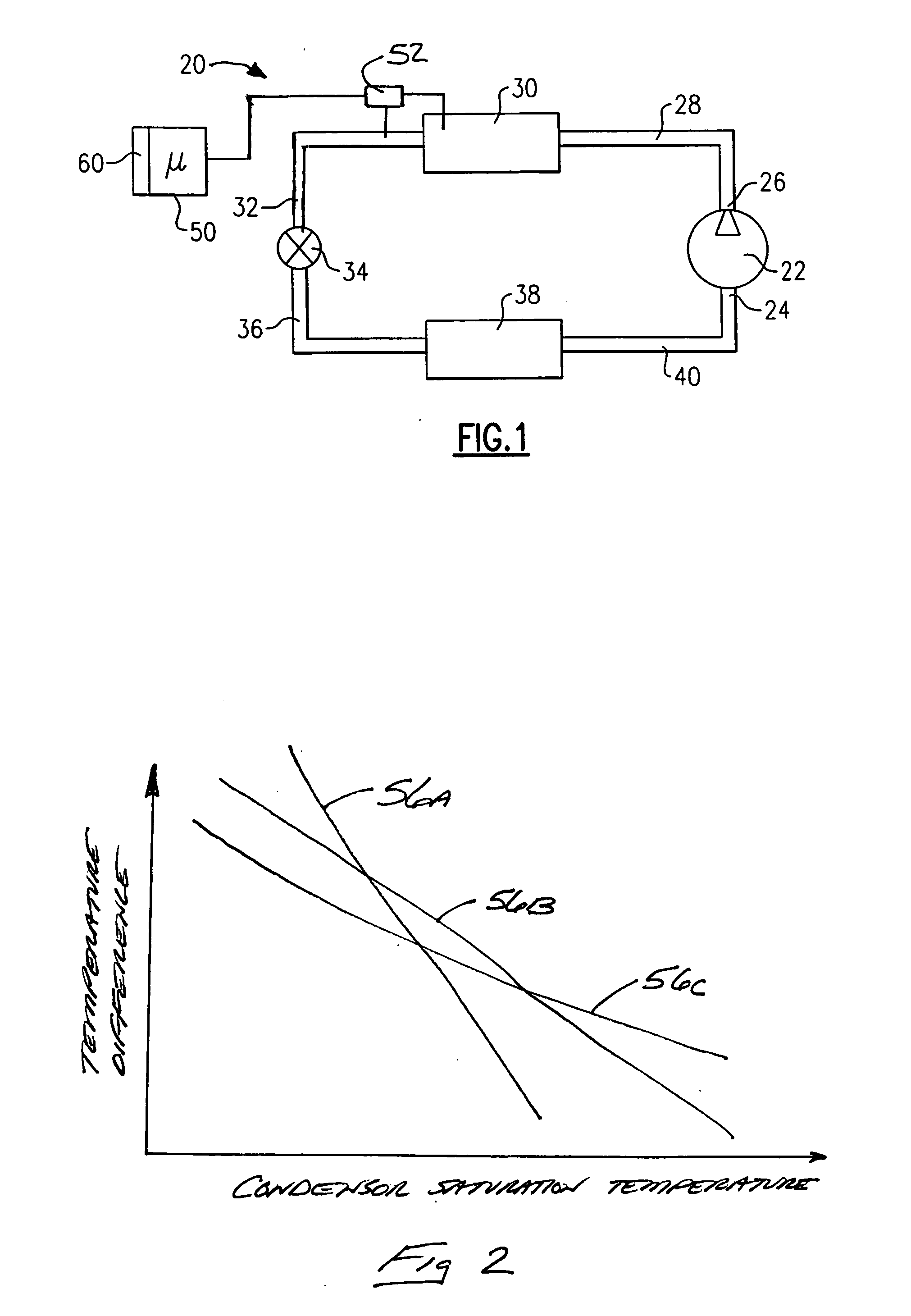
[0014]FIG. 1 schematically shows a refrigerant system 20 that may be used as an air conditioning system, heat pump or a refrigeration system. A compressor 22 draws refrigerant from a suction port 24 and provides a compressed gas under pressure to a compressor discharge port 26. The high temperature, pressurized gas flows through a conduit28 to a condenser 30 where the gas dissipates heat and condenses into a liquid as known. The liquid refrigerant flows through a conduit 32 to an expansion device 34. As the refrigerant in the conduit 32 typically is in a liquid state, the conduit 32 is sometimes referred to as the liquid line.

[0015] In one example, the expansion device 34 operates in a known manner to allow the liquid refrigerant to be expanded and to partially evaporate and flow into a conduit 36 in the form of a cold, low pressure refrigerant. This refrigerant then flows through an evaporator 38 where the refrigerant absorbs heat from air that flows across the evaporator coils, w...


PUM


Abstract

An air conditioning, heating or refrigeration system includes a controller that automatically determines if refrigerant amount is above or below the desired amount within the system. In one example, a sensor measures the temperature difference between sub-cooled liquid and saturated condensing temperature and provides information to the controller. The controller determines a variance between the measured and an expected value. If that variance exceeds a selected threshold, the controller automatically determines that the amount of refrigerant in the system is outside of an acceptable range.

Description

FIELD OF THE INVENTION [0001] This invention generally relates to refrigerant systems. More particularly, this invention relates to monitoring an amount of refrigerant charge within an air conditioning or refrigeration system. DESCRIPTION OF THE RELATED ART [0002] Air conditioning and refrigeration systems typically utilize a refrigerant to achieve a desired amount of cooling within a building, for example. Having an adequate amount of refrigerant within the system is necessary to achieve a desired system operation and to prevent malfunctions or damage to the system components. Many systems are charged at a factory. Others are charged by a technician after installation in the field. [0003] It is possible for the refrigerant charge in the system to be initially too low or for some refrigerant to be lost or reduced during operation to a level that hinders the ability of the system to provide adequate cooling. At some levels, a loss of refrigerant charge may cause damage to the system ...

Claims


Application Information

Patent Timeline
IPC IPC(8): F25B15/00F25B45/00F25B49/00G05B23/02
CPCF25B49/005F25B2700/21163F25B2700/2116
Inventor DOBMEIER, THOMAS J.TARAS, MICHAEL F.LIFSON, ALEXANDER
Owner CARRIER CORP
Why Eureka
Try Eureka