Structure of Peltier Element or Seebeck Element and Its Manufacturing Method

a technology of peltier elements and manufacturing methods, applied in the direction of thermoelectric devices, photomechanical devices, instruments, etc., can solve the problems of adverse effects on the environment, decrease in adverse effects on the natural world, etc., to reduce the movement of thermal energy, increase the use efficiency of thermal energy, and reduce the manufacturing cost of the element

Inactive Publication Date: 2009-01-08
MEIDENSHA ELECTRIC MFG CO LTD +2
View PDF3 Cites 85 Cited by
  • Summary
  • Abstract
  • Description
  • Claims
  • Application Information

AI Technical Summary

Benefits of technology

[0017]The present invention has been devised to solve the above-mentioned problem. It is an object of the present invention to provide a Peltier element or a Seebeck element with a new structure and its manufacturing method. Especially, shapes (or materials) of a first conducti...

Problems solved by technology

In general, the thermal energy discharged to the natural world is not used for the human, and conversely may affect the natural world adversely.
It is problematic that use efficiency of the thermal energy is decreased with increase of the energy used for the elimination and the removal of the thermal energy.
However, in fact, the inexhaustible thermal energy which is final form of the energy, and which exists in the natural world can not reuse positively, without input of the new energy, to decrease the adverse effect on the environment.
Due to difference in the number of free electrons in the two conductors, the electrons move between the two conductors, resulting in a potential difference between the two conductors.
That is, in the Seebeck element, the heat part and the cool part interfere thermally with each other.
In the Peltier element, the heat absorption part and the heat generation part interfere thermally with each other.
Accordingly, in a case in which extensive energy conversion provision are built up by using the above-described Peltier element and Seebeck element, new heat engines are needed in installation location of that provision and so on, and it is unreal for this physical limitation.
Accordingly, as shown in FIG. 44, in the case in which the conventional pai type Seebeck element or the Peltier element is assembled, it is problematic that the flow of the thermal energy from the high temperature side to the low temperature side of each element by the heat conduction can not be ignored.
Consequently, it is not possible to take the heat from the circumference, and it is problematic that the heat transfer can not be performed.
It is pro...

Method used


Image

  • Structure of Peltier Element or Seebeck Element and Its Manufacturing Method
  • Structure of Peltier Element or Seebeck Element and Its Manufacturing Method
  • Structure of Peltier Element or Seebeck Element and Its Manufacturing Method

Examples


first embodiment

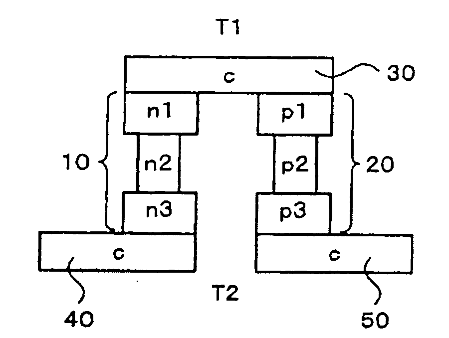
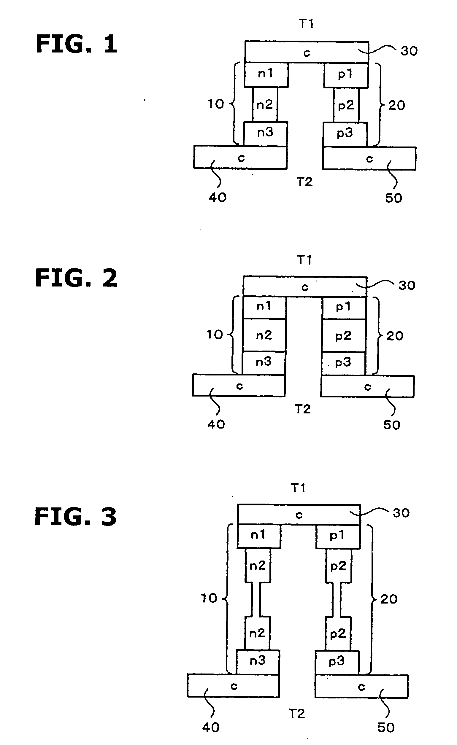
[0068]Hereinafter, a structure of a Peltier element or a Seebeck element according to the present invention and its manufacturing method will be illustrated with reference to the drawings. FIG. 1 is a diagrammatic view showing a structure of a Peltier element or a Seebeck element according to the present invention.

[0069]As shown in FIG. 1, a first conductive member (a n-type semiconductor and so on) 10 having a predetermined Seebeck coefficient is composed of both end parts n1 and n3 thereof, and an intermediate part n2. Moreover, a second conductive member (a p-type semiconductor and so on) 20 having a Seebeck coefficient different from the Seebeck coefficient of the first conductive member is composed of both end parts p1 and p3 thereof, and an intermediate part p2.

[0070]The intermediate parts n2 and p2 of the first conductive member 10 and the second conductive member 20 have cross sections which are smaller than cross sections of the both end parts n1, n3, p1 and p3. Accordingly...

second embodiment

[0075]In this way, in FIG. 1, the intermediate parts of the first conductive member 10 and the second conductive member 20 have the cross sections which are smaller than the cross sections of the both end parts thereof, so that the thermal conductivities become small. In the present invention, for example, as shown in FIG. 2, the first conductive member 10 and the second conductive member 20 have the same cross sectional shape. It is optional to use, as material of the intermediate parts n2 and p2, for example, material with a thermal conductivity which is smaller than a thermal conductivity of both end parts n1, p1 or n3, p3, such as amorphous silicon and polysilicon.

third embodiment

[0076]Moreover, in the present invention, as shown in FIG. 3, the intermediate parts n2 and p2 of the first conductive member 10 and the second conductive member 20 are further divided to form constrictions (for example, to form narrow width portions in the intermediate parts of the first conductive member 10 and the second conductive member 20). That is, it is optional to form shapes with small cross sections by dividing the intermediate parts n2 and p2 itself into a plurality of parts. Thereby, it is possible to further decrease the thermal conductivities of the intermediate parts n2 and p2, and to decrease the semiconductor material. Consequently, it is possible to further increase the temperature difference between the high temperature side and the low temperature side.

[0077]In the Peltier / Seebeck elements according to the embodiments of the present invention as shown in FIGS. 1˜3, for providing function to enhance the Peltier effect or the Seebeck effect, the first conductive m...


PUM


Abstract

A Peltier or Seebeck element has first and second conductive members having different Seebeck coefficients. To decrease the heat conduction from one to the other end of each of the conductive members, the cross-section area at the intermediate part in the length direction is smaller than those at both ends parts. In place of the decrease of the cross-section, the shape of the cross-section of the intermediate part of each of the conductive members may be changed by dividing the intermediate part into pieces, or amorphous silicon or the like having a heat conductivity lower than those of the materials of both end parts may be used for the material of the intermediate part. In such a way, a high-performance Peltier/Seebeck element such that the difference between the temperature of the heated portion of the Peltier/Seebeck element and the opposite portion can be kept to a predetermined temperature difference for a long time and its manufacturing method are provided.

Description

TECHNICAL FIELD[0001]This invention relates to a structure of an element to enhance a function of a Peltier element or a Seebeck element used in a thermoelectric conversion system or a thermoelectric conversion apparatus which is arranged to convert thermal energy in all portions, spaces and regions that a temperature is increased, such as buildings and objects that heat from outside due to various electronics, combustion apparatuses, its related equipments, sun light, geotherm and so on is affected, and its manufacturing process.BACKGROUND ART[0002]Energy in natural world is used irreversibly, becomes thermal energy at last, and discharged to the natural world. In general, the thermal energy discharged to the natural world is not used for the human, and conversely may affect the natural world adversely. Therefore, for eliminating and removing this thermal energy, a forcible air cooling and a forcible water cooling are performed by using energy and electric energy by further new hea...

Claims


Application Information

Patent Timeline
IPC IPC(8): H01L35/28G03F7/20
CPCH01L35/32H10N10/17
Inventor KONDOH, YOSHIOMIIWASAWA, NAOTAKA
Owner MEIDENSHA ELECTRIC MFG CO LTD
Why Eureka
Try Eureka