Sippy cup valve

Inactive Publication Date: 2005-09-22
EVENFLO CO INC
View PDF33 Cites 32 Cited by
  • Summary
  • Abstract
  • Description
  • Claims
  • Application Information

AI Technical Summary

Benefits of technology

[0009] The present invention is directed to a valve, and more specifically to an automatic valve for a beverage dispenser providing for selective ingress of gas into the dispenser and selective egress of liquid from the dispenser. The valve is adapted to regulate the flow of gas into, and the flow of liquid from, the beverage dispenser. As will be discussed in more detail below, at least a portion of the valve is adapted to be removable from a beverage dispenser lid and work in tandem with the configurations of the lid to facilitate selective egress of liquid from the beverage dispenser.
[0010] The valve of the present invention comprises an elastomeric insert adapted to interface with features on the underneath surface of a beverage dispenser lid. The insert is mounted to the lid, at least in part, by a combination snap-fit and a friction fit. Orifices in the lid correspond with a spout for withdrawal of liquid from the dispenser and an air intake to facilitate the withdrawal through the spout. The elastomeric insert deforms under the siphoning conditions to provide direct fluid communication between the liquid within the dispenser and the opening in the spout. If the siphoning discontinues or the siphon is not strong enough, the insert will not sub

Problems solved by technology

If the siphoning discontinues or the siphon is not strong enough, the insert will not substantially de

Method used


Image

  • Sippy cup valve
  • Sippy cup valve
  • Sippy cup valve

Examples


Embodiment Construction

[0016] The exemplary embodiments of the present invention are described and illustrated below to encompass valves, systems, and methods for regulating the flow of liquid from a beverage dispenser. Of course, it will be apparent to those of ordinary skill in the art that the preferred embodiment discussed below is exemplary in nature and may be reconfigured without departing from the scope and spirit of the present invention. However, for clarity and precision, the exemplary embodiment includes one or more optional features that one of ordinary skill may recognize as not being a requisite to fall within the scope of the present invention.

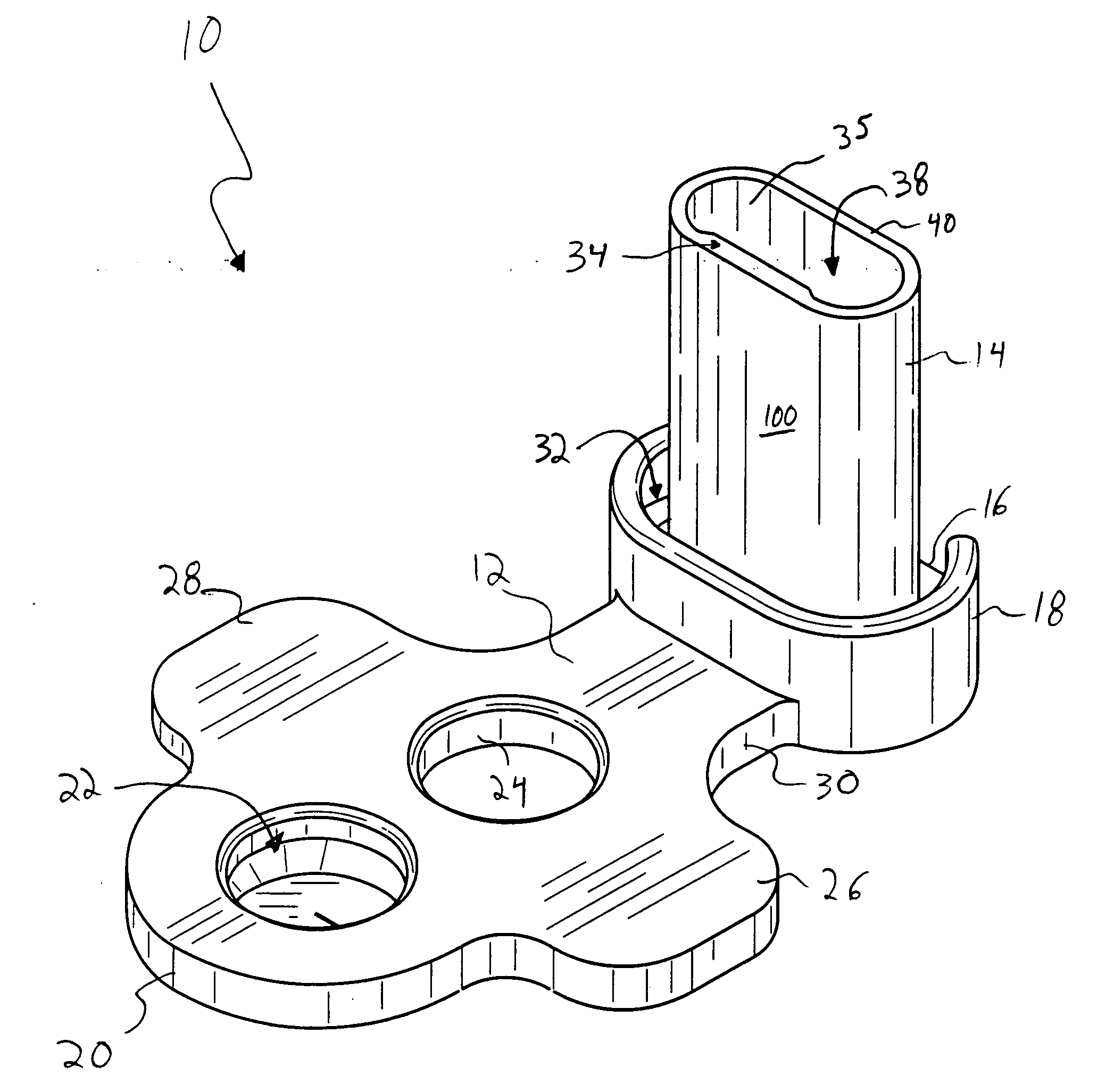
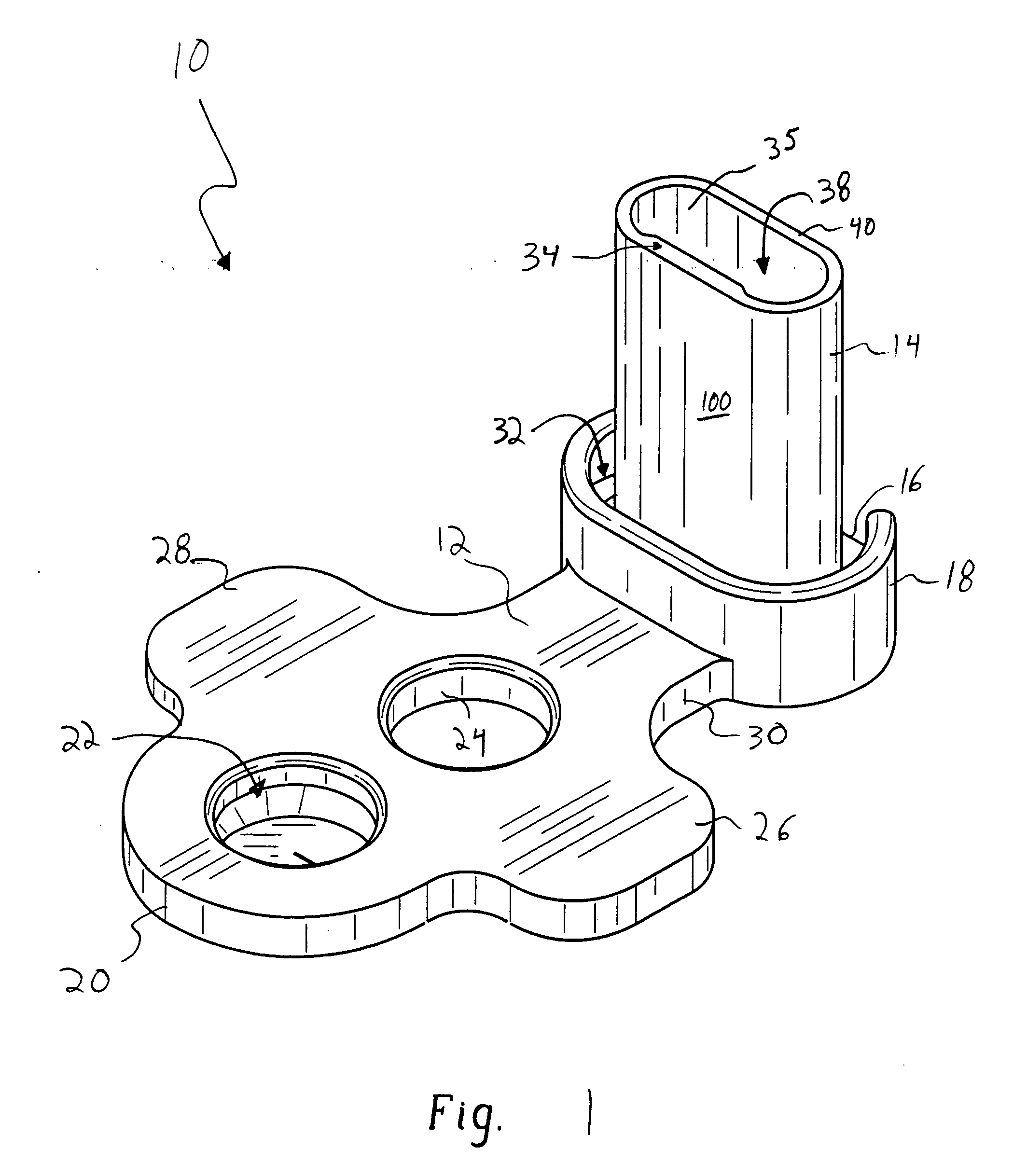
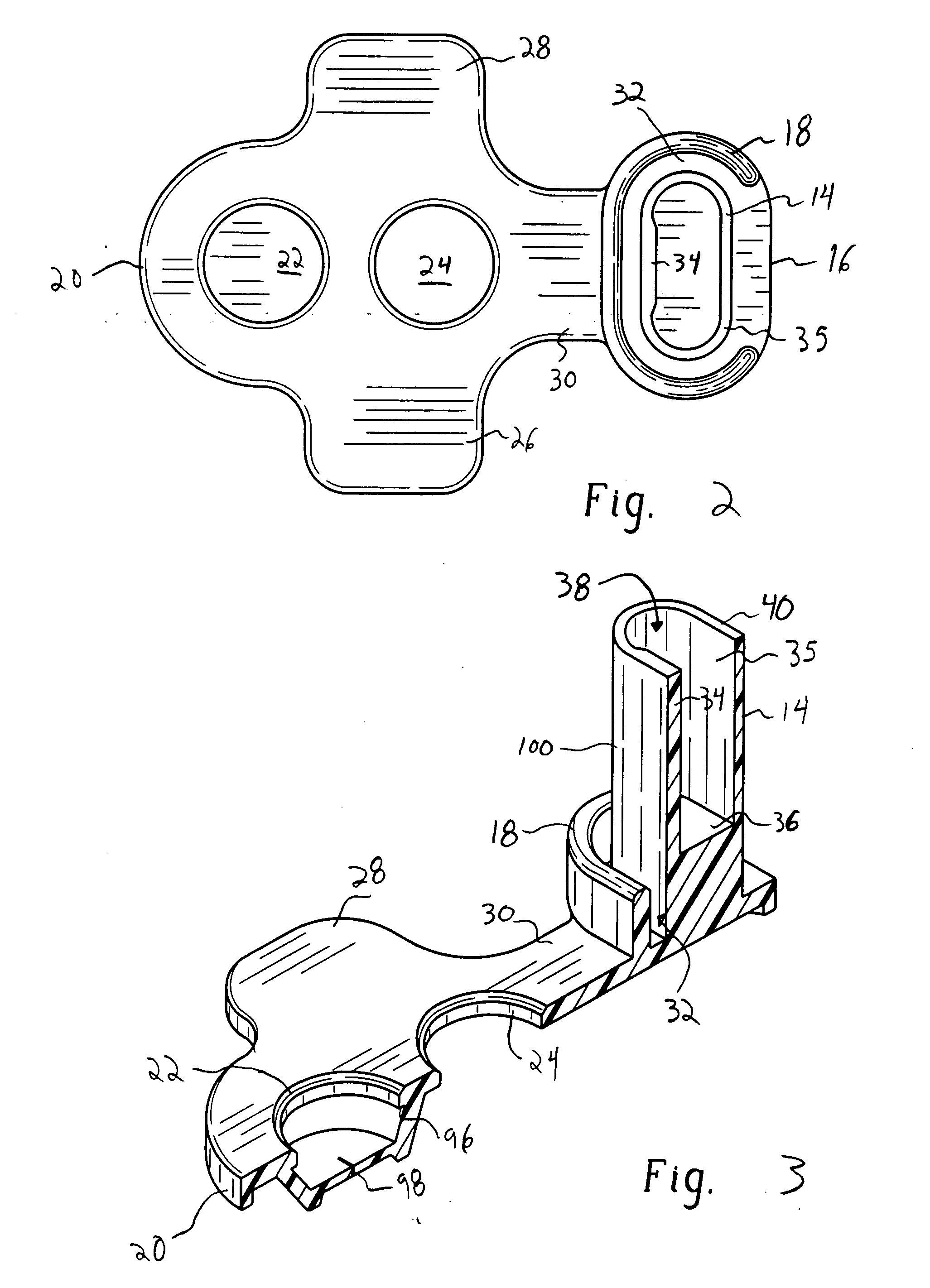
[0017] Referencing FIGS. 1-3, an exemplary valve insert 10 in accordance with the present invention includes a platform 12 having a tower 14 at a first longitudinal end 16 at least partially circumscribed by a raised wall 18. A second longitudinal end 20 includes a depression 22 extending through the platform 12 and adjacent to a circular opening 24...


PUM


Abstract

A spill-proof beverage dispenser comprising: (a) a container adapted to at least partially define an interior volume available for occupation by a liquid; (b) a lid adapted to be mounted to the container, the lid including a vent and a dispensing opening, and a liquid conduit having a passageway therethrough in fluid communication with the liquid within the container and selective fluid communication with the dispensing opening; and (c) a valve assembly mountable to the lid including a collapsible tower adapted to be received at least partially within the liquid conduit to selectively restrict liquid flow between the interior volume of the container and the dispensing opening, the collapsible tower being responsive to changes in pressure by collapsing at least one wall of the collapsible tower to selectively provide fluid communication between the passageway and the dispensing opening.

Description

BACKGROUND [0001] 1. Field of the Invention [0002] The present invention is directed to a valve, and more specifically to an automatic valve for a spill-proof type beverage dispenser. [0003] 2. Background of the Invention [0004] Spill-proof beverage dispensers are known in the art and are utilized most notably for the purpose of preventing inadvertent spillage of liquid from a beverage dispenser, such as a cup. For example, if a spill-proof cup is dropped or knocked over, it is intended that a majority of the liquid be retained therein. The retention of liquid therein lessens the waste associated with spilled beverages, reduces the work associated with beverage spill cleanup, and reduces potential economic consequences of destruction caused by any such spillage. More specific applications of spill-proof beverage dispensers may be directed to children's cups where one or more valves are incorporated or mounted therein, allowing the child to remove liquid from the cup when in the act ...

Claims


Application Information

Patent Timeline
IPC IPC(8): A47G19/22F16K15/14
CPCF16K15/142A47G19/2272
Inventor DAVIS, DENNIS L.YEE, CHUNGKINOGLE, BRYAN R.
Owner EVENFLO CO INC
Why Eureka
Try Eureka