

Floating captive screw
a captive screw and floating technology, applied in the direction of screws, threaded fasteners, load-modified fasteners, etc., can solve the problems of detrimental heat transfer effect, microchips during operation getting warmer and warmer, and standoffs not compensating
- Summary
- Abstract
- Description
- Claims
- Application Information
AI Technical Summary
Benefits of technology
Problems solved by technology
Method used
Image

Examples
third embodiment
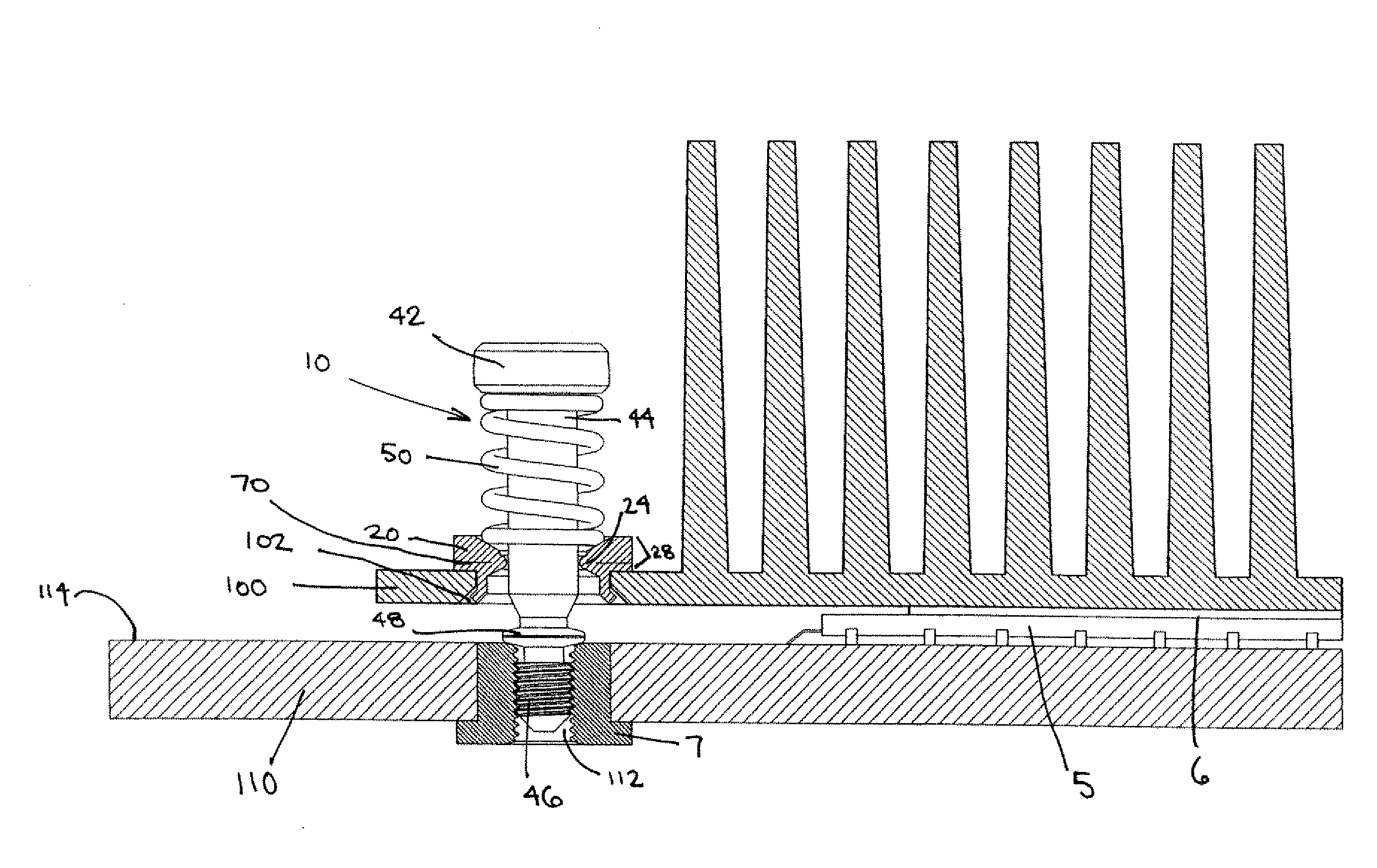
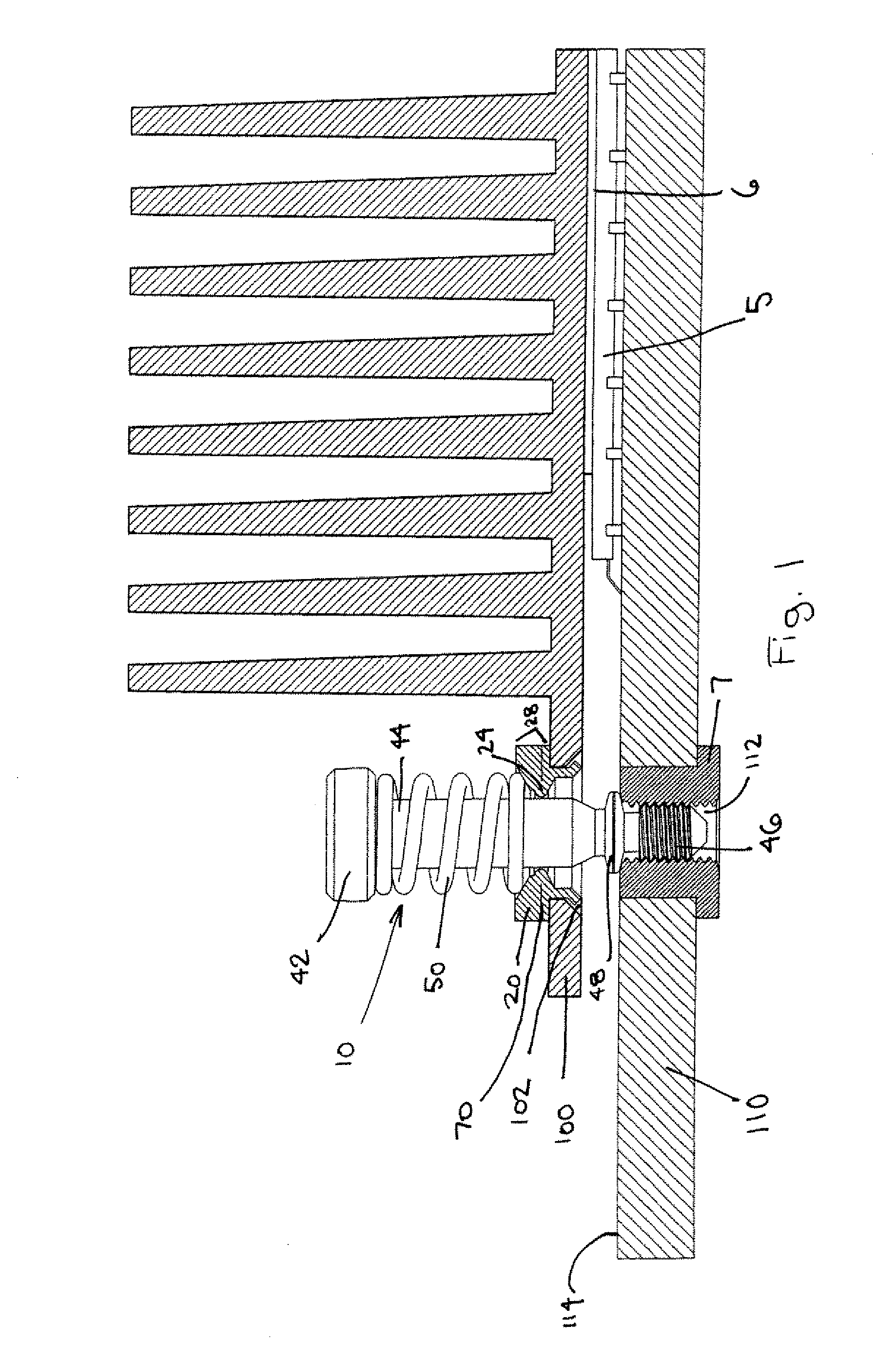
[0046] In the invention as shown in FIGS. 17 and 18, the ferrule 220 also has a first annular lip 58 or stop formed on the exterior cylindrical surface proximate the top of the ferrule 220 for limiting the penetration of the ferrule 220 in the preformed aperture 102 in the first structure, as well as an annular circumferential groove 130 formed in the exterior cylindrical surface of the ferrule immediately adjacent and below the first annular lip 58, for receiving the plastic flow of material 104 when the ferrule 220 is pressed into the preformed aperture. A second annular lip 68 is shown at the opposite end of the ferrule. When the captive screw of 210 the present invention is installed, the collar 48 precisely limits the vertical position of the screw 40 above the second structure (not shown), while the first structure 100 floats above the second structure, while being urged towards the second structure by the spring 50 of the captive screw 210. In this embodiment of the present i...
fourth embodiment
[0047] In the fourth embodiment, FIGS. 19, 20, 21 and 22 show a captive screw in first structure 100 having a collar 148 which has outwardly extending legs and a base portion. The collar has outwardly extending legs 248 and the base portion 348. The ends 448 of the legs 248 extend outwardly and define a collar cross section. Since the legs are flexible, the ends of the legs deform elastically and permit the collar to pass through a first structure when being passed through an aperture in a structure and the aperture has a smaller cross section than that defined by the ends of the legs. The arrangement shown in FIG. 19 is one way in which to install the collar 48 into a second structure 110. The base portion 348 of the collar limits the penetration of the screw into the second structure. In the embodiment shown in FIG. 20 the ends 448 of the legs contact the underside of the first structure. The collar can be in the shape of a crown and the collar can be threaded on, crimped on or pr...
PUM
 Abstract
Description
Claims
Application Information