Organic electro phosphorescent device and its preparation method

A phosphorescent device and electrophosphorescence technology, applied in electroluminescent light sources, chemical instruments and methods, electric light sources, etc., can solve problems such as luminous efficiency and brightness limitations, and achieve improved luminous efficiency and brightness, improved utilization, and expanded The effect of glowing areas

Active Publication Date: 2005-02-16
BEIJING VISIONOX TECH
View PDF1 Cites 30 Cited by
  • Summary
  • Abstract
  • Description
  • Claims
  • Application Information

AI Technical Summary

Problems solved by technology

Therefore, for uniformly doped phosphorescent devices, only the dyes located in the light-emitting r

Method used


Image

  • Organic electro phosphorescent device and its preparation method
  • Organic electro phosphorescent device and its preparation method
  • Organic electro phosphorescent device and its preparation method

Examples


Embodiment 1

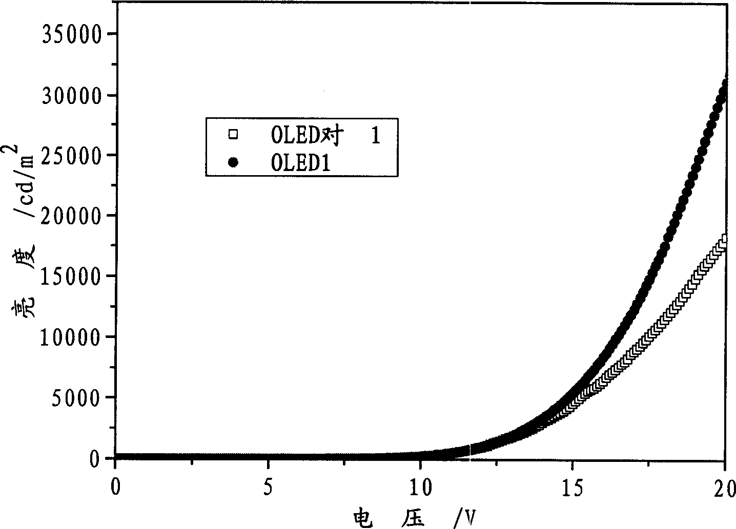
[0091] Embodiment 1 (device number OLED1)

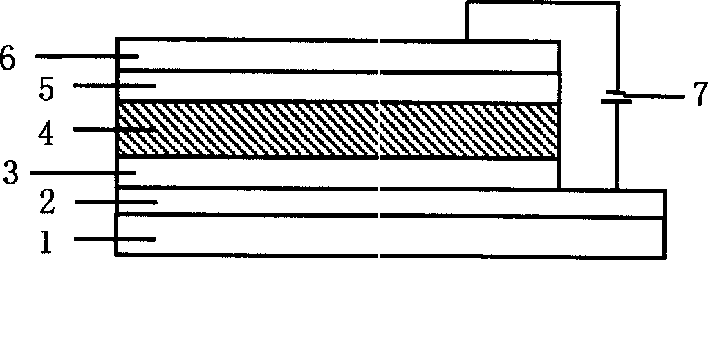
[0092] OLED1 was prepared by the same method as the above-mentioned preparation of the device represented by structural formula (1).

Embodiment 2

[0095] Embodiment 2 (device number OLED2)

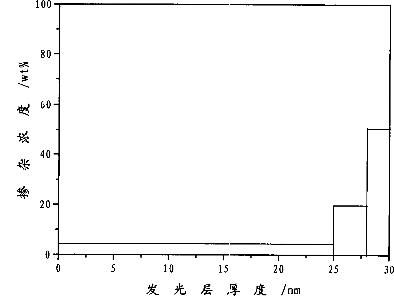
[0096] Prepare OLED2 with the same method as the device shown in the above-mentioned preparation structural formula (1), wherein the host material of the organic light-emitting layer of the device adopts CBP, and the phosphorescent dye adopts Ir(ppy) 3 , by controlling the evaporation rate ratio of dual-source evaporation to make Ir(ppy) 3 The doping concentration in CBP decreases gradually with the increase of the evaporation thickness of the organic light-emitting layer.

Embodiment 3

[0099] Embodiment 3 (device number OLED3)

[0100] Prepare OLED3 with the same method as the device shown in the above-mentioned preparation structural formula (1), wherein the host material of the organic light-emitting layer of the device adopts CBP, and the phosphorescent dye adopts Ir(piq) 2 (acac), by controlling the evaporation rate ratio of dual-source evaporation to make Ir(piq) 2 The doping concentration of (acac) in CBP decreases gradually with the increase of the evaporation thickness of the organic light-emitting layer.


PUM

PropertyMeasurementUnit
Film thicknessaaaaaaaaaa

Abstract

The present invention relates to an organic electro phosphorescent device and its preparation method. Said device comprises a transparent base sheet, an anode layer, organic functional layer and a cathode layer, wherein the organic functional layer comprises organic luminous layer and one ore more layers selected from a positive hole injection layer, a positive hole transport layer, an electronic transport layer and an electron injection layer, said organic luminous layer includes a body material and a phosphorescent coloring agent, the doping concentration of said phosphorescent coloring agent gradually rises or drops with the thickness increase of the organic luminous layer to form a gradient doping structure. For said device, by doping the phosphorescent coloring agent into the body material in the organic luminous layer with a gradient doping manner, the luminous area of the device is expanded and the use ratio of the phosphorescent coloring agent is improved; it is also helpful to the exciton formation from electronic and positive hole, then light-emitting efficiency and lighteness of the device are improved, and the stability is improved; at the same time, the shortcomings of low light-emitting efficiency and poor stability of the device under large electric current are overcome.

Description

technical field [0001] The invention relates to an organic electroluminescence device and a preparation method of the device, belonging to the technical field of organic electroluminescence. Background technique [0002] Today, with the development of multimedia technology and the advent of the information society, the requirements for the performance of flat panel displays are getting higher and higher. In recent years, three new display technologies: plasma display, field emission display and organic electroluminescent display have made up for the shortcomings of cathode ray tubes and liquid crystal displays to a certain extent. Among them, the organic electroluminescent display has a series of advantages such as self-illumination, low-voltage DC drive, full curing, wide viewing angle, and rich colors. Low, its response speed can reach 1000 times that of liquid crystal display, but its manufacturing cost is lower than the liquid crystal display of the same resolution, the...

Claims


Application Information

Patent Timeline
IPC IPC(8): H05B33/14H05B33/20H05B33/12H05B33/10C09K11/06
Inventor 邱勇雷钢铁王立铎
Owner BEIJING VISIONOX TECH
Why Eureka
Try Eureka