
Protective sleeve

a protection sleeve and sleeve technology, applied in the direction of rod connection, shock absorber, fluid actuated brake, etc., can solve the problems of damage to the protective sleeve, the protection sleeve often does not fold properly during the entry of the piston, etc., to facilitate the proper folding or withdrawal of the protective sleeve

Active Publication Date: 2005-09-22
CARL FREUDENBERG KG
View PDF10 Cites 2 Cited by
  • Summary
  • Abstract
  • Description
  • Claims
  • Application Information

AI Technical Summary

Benefits of technology

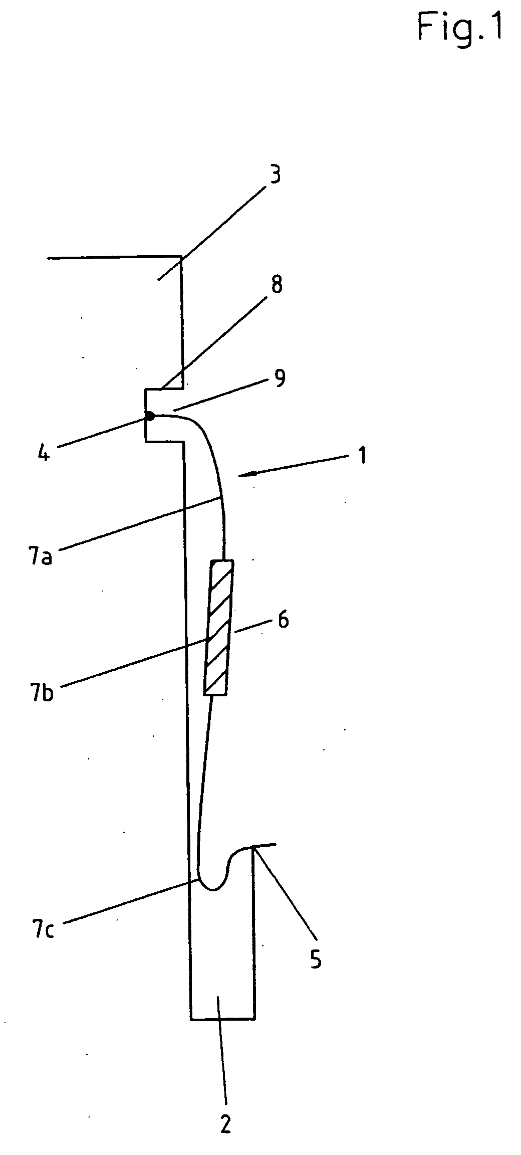
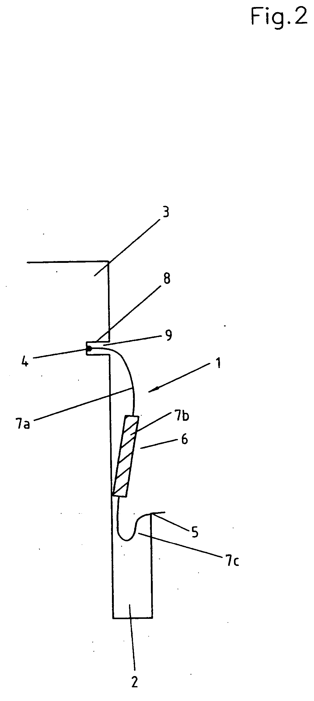
[0006] The stiffening zone is preferably essentially annular. This means that it must extend around he periphery of the longitudinal segment in a manner such that radial stretching of the sleeve in this region is prevented. Preferably, the stiffening zone is positioned in a region that is especially exposed to the risk of bulging out during piston entry. The stiffening zone, however, does not necessarily have to be closed along the entire periphery. According to the present invention, during piston entry, the annular stiffening zone not only prevents radial bulging of the sleeve in the region at risk, but in addition, also serves as a guiding element on which the elastic longitudinal segments of the protective sleeve unroll or support themselves, which additionally facilitates the folding-in process.
[0009] The stiffness can be increased, for example, by enveloping the longitudinal segment in question in the stiffening zone with a material of higher stiffness, or by entirely replacing the elastic material in this zone with a material of higher stiffness. Another alternative is to incorporate such a material of higher stiffness into the elastic material. The stiffening material, however, does not necessarily have to extend around the entire periphery of the stiffening zone and / or be firmly linked with the sleeve material.
[0011] In a preferred embodiment of the invention, the increased stiffness is achieved in simple fashion by increasing the wall thickness of the sleeve in this region. In another preferred embodiment of the invention, a stiffness ring is provided in a simple manner by enveloping the elastic material with a ring made of a stiffer material such as, for example, metal or a firm plastic. Another alternative invovles incorporating such a ring into the elastic material.
[0014] In another preferred embodiment of the invention, the annular end bulge is connected with the sleeve wall by means of a film hinge formed by a local annular reduction in a bellows wall thickness. This measure, which can be applied even without stiffened longitudinal segments, also facilitates the proper folding or withdrawing of the protective sleeve.

Problems solved by technology

These known protective sleeves have the drawback, however, that, particularly when the space for installation is small and the stroke of the piston is long, the protective sleeve often does not fold properly during the entry of the piston.
Because the part cannot be seen when it is installed, the flawed folding of the sleeve often goes unrecognized which results in possible damage to the protective sleeve.

Method used


Image

  • Protective sleeve
  • Protective sleeve
  • Protective sleeve

Examples


Embodiment Construction

[0019] The following description of the preferred embodiment(s) is merely exemplary in nature and is in no way intended to limit the invention, its application, or uses.

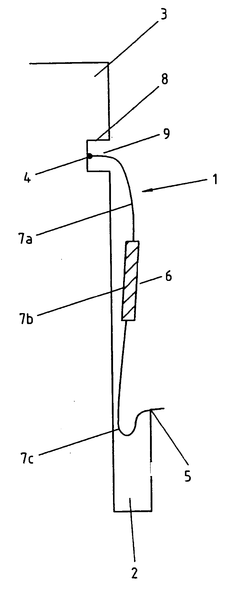
[0020]FIG. 1 depicts a protective sleeve 1 made of an elastic material for a piston-cylinder unit having a piston 3 disposed in a cylinder bore 2 in an axially displaceable manner. The protective sleeve 1 is provided with annular end segments 4 and 5 that can be supported on one side on the outer piston wall 3, and on the other side in the cylinder bore 2. The protective sleeve also has a middle segment 6 that is essentially a hollow cylindrical shape which connects the two end segments. When the piston 3 is in its entered position, as shown in FIG. 3, the middle segment 6 is folded like rag in a radial direction as in a bellows. By “of essentially hollow cylindrical shape” is meant here that the middle segment 6 can taper off or became wider in a conical fashion.

[0021] According to the invention, the middle segmen...


PUM


Abstract

A protective sleeve made of an elastic material for a piston-cylinder unit with a piston disposed in a cylinder bore in an axially displaceable manner. The protective sleeve is provided with annular end segments that can be supported on the outer piston wall on one side and in the cylinder bore on the other. A middle segment of an essentially hollow cylindrical shape connects the two end segments with each other and, when the piston is in an entered position, is folded like a rag in a radial direction as in a bellows. To ensure reliable and correct folding of the protective sleeve during the entry of the piston, the middle segment is subdivided in the axial direction into annular longitudinal segments, the lengths of which are approximately equal to the length of a fold wall, and at least one of the longitudinal segments is provided with an essentially annular stiffening zone.

Description

CROSS-REFERENCE TO RELATED APPLICATIONS [0001] This application claims the benefit of German Patent applications 10 2004 007 441.0, filed Feb. 13, 2004; 10 2004 007 735.5, filed Feb. 16, 2004; and 10 2004 008 421.1, filed Feb. 19, 2004. The disclosures of the above applications are incorporated herein by reference. FIELD OF THE INVENTION [0002] The present invention relates to a protective sleeve made of an elastic material for a piston-cylinder unit with a piston disposed in a cylinder bore in axially displaceable manner. The protective sleeve has annular end regions supported on an outer piston wall on one side and in the cylinder bore on the other. When the piston is in a pulled-out position a middle region of an essentially hollow cylindrical shape connects the two end regions to one another. When the piston is in an entered position, the middle region is folded like a rag in a radial direction as in a bellows. DESCRIPTION OF THE RELATED ART [0003] Protective sleeves of the afor...

Claims


Application Information

Patent Timeline
Patent Type & Authority Applications(United States)
IPC IPC(8): D06C29/00F16F9/04F16F9/36F16F9/38F16J15/56
CPCF16D65/00Y10T403/31F16F9/38
Inventor SCHNEIDER, ECKHARD
Owner CARL FREUDENBERG KG
Learn More