
Novel circular tube slitting mill

A rolling cutting machine and pipe material technology, which is applied in the direction of pipe shearing devices, shearing devices, and attachments of shearing machines, etc., can solve the difficulty in aligning the clamping center and rolling cutting center of the clamping device, and the difficulty in controlling the separation time of the clutch , the length of the cantilever of the rotary hobbing mechanism, etc., to achieve the effects of improving stability and centering reliability, accurate knife retraction time, and reducing the length of the cantilever

Inactive Publication Date: 2009-06-03
YANSHAN UNIV
View PDF1 Cites 18 Cited by
  • Summary
  • Abstract
  • Description
  • Claims
  • Application Information

AI Technical Summary

Problems solved by technology

After in-depth research, the inventors of the present invention have proposed solutions to the long cantilever of the rotary hobbing mechanism, the impact generated when starting, the separation time of the clutch is not easy to control, and the hobbing device stops relative to the inner cam after the knife is retracted. The position is not accurate enough, and the solution to the problems of the clamping center of the clamping device and the centering of the hobbing center is difficult, and the present invention is completed on this basis

Method used


Image

  • Novel circular tube slitting mill
  • Novel circular tube slitting mill
  • Novel circular tube slitting mill

Examples


Embodiment Construction

[0018] The present invention is described in detail below in conjunction with accompanying drawing embodiment:

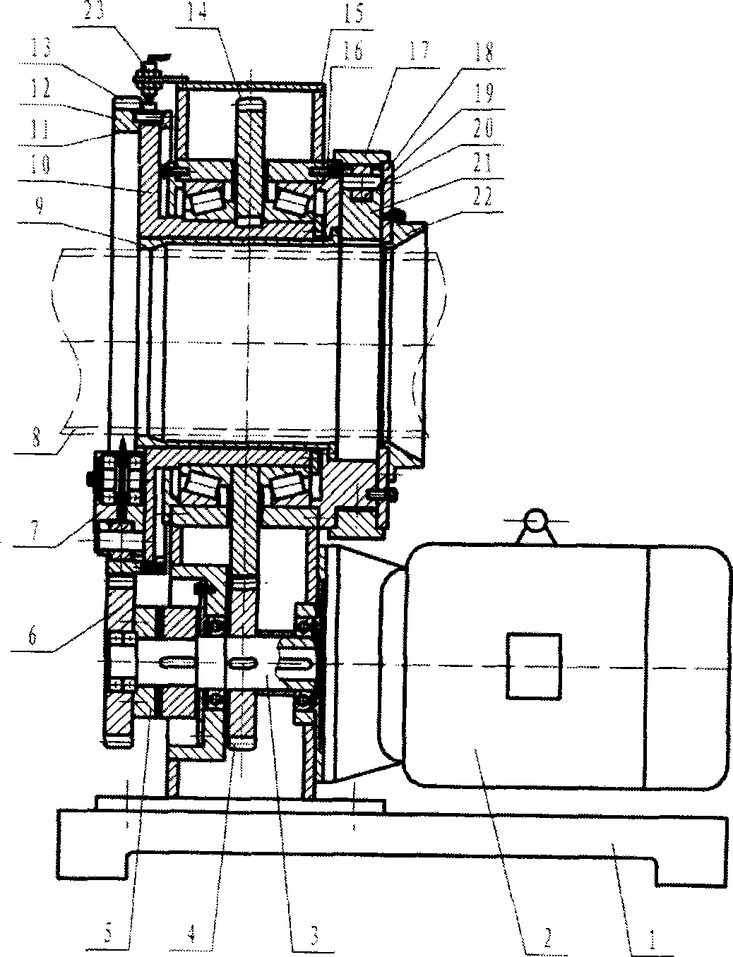
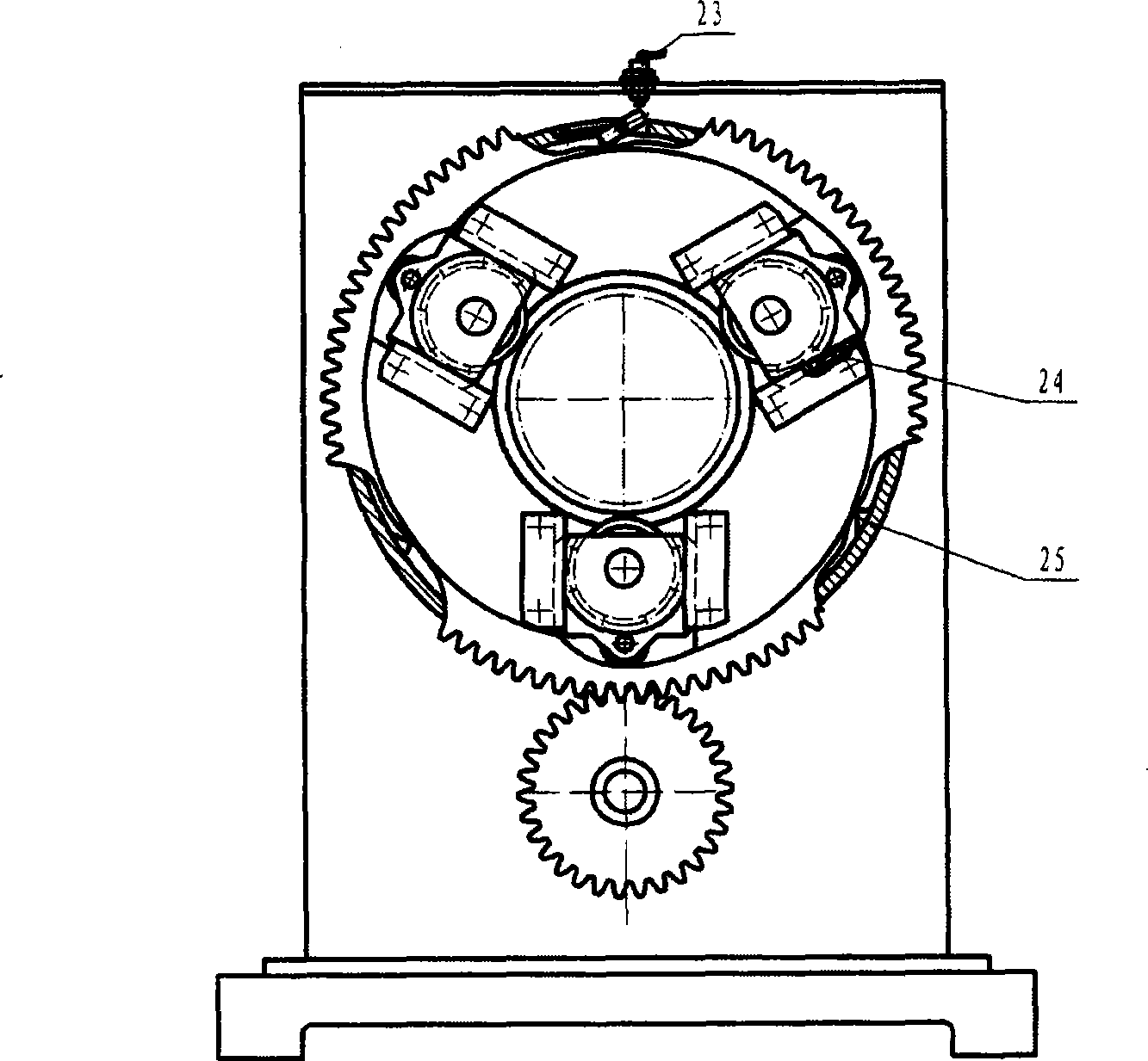
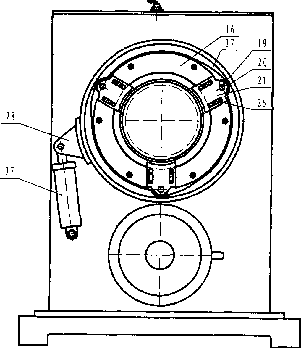
[0019] Depend on figure 1 , figure 2 , image 3 The shown circular section pipe rolling cutting machine includes a frame 15 installed on the base 1, and a transmission shaft 3 is installed at the lower part of the frame 15; one end of the transmission shaft 3 is connected with the output shaft of the motor 2, reducing The transmission link is improved, the efficiency is improved, and the equipment is more compact. The transmission shaft 3 is provided with a clutch 5 and a transmission pinion 4 and a hobbing pinion 6 arranged on both sides; a relative frame 15 is installed in the inner hole of the upper part 15 of the frame through a bearing (not marked in the figure). Rotating disk shaft 10; fixedly installed transmission bull gear 14 on the disk shaft 10 between the bearings; and a rotating ring 12 installed on the disk outer ring of the disk shaft 10. The out...


PUM


Abstract

The invention discloses a novel circular-section tube slitting mill comprising transmission members respectively arranged on a transmission shaft and transmission members which are correspond to a disk shaft and connected with rotable loops located thereon. A hobbing device is arranged inside a radial sliding chute of the disk head face of the disk shaft, wherein, the hobbing device is provided with an internal circle that is a cam ring, and an external circle is a rotatable loop hobbing a bull gear and is installed on the external circle ring of the disk of the disk shaft; the rotatable loop, disk shaft and a stander are provided with a start-and-retract control device; and a clamping device is installed at the tubular product feeding end of the stander. As the rotatable loop directly rotates along the external circle of the disk shaft, the axial size is reduced, the stress condition is obviously improved and the vibration is avoided; as the start-and-retract control device is provided, accurate slitting moment of cluster is guaranteed at the time of starting, and start impact is avoided; when the hobbing device retracts, the device stops at a maximum retracting position of the cam ring; meanwhile, the clamping device is added and installed, thereby improving the stability and centering reliability for clamping tubular products.

Description

technical field [0001] The present invention relates to a kind of pipe cutting equipment, in particular to a new type of round pipe rolling cutting machine, which can effectively reduce the eccentric vibration tendency of the rolling cutting mechanism, overcome the starting impact, improve the accuracy of the retracting time and the reliability of clamping and centering sex. Background technique [0002] At present, the hobbing machine used for cutting circular cross-section pipes or cutting pipes on the round pipe production line, when the pipe is not allowed to rotate, the hob must revolve around the center of the pipe, and at the same time the hob rolls along the pipe surface and moves toward the center Movement, to achieve the purpose of cutting off the pipe. [0003] For the above-mentioned technology for cutting circular section pipes, such as the Chinese invention patent, its application number is "Circular Section Pipe Rolling Cutting Machine" disclosed in 200610012...

Claims


Application Information

Patent Timeline
Patent Type & Authority Applications(China)
IPC IPC(8): B23D21/04B23D33/00B23D33/02
Inventor 刘庆国
Owner YANSHAN UNIV
Learn More