
Catheter pump, catheter and fittings therefore and methods of using a catheter pump

a catheter and pump technology, applied in the direction of catheters, catheters, heart stimulators, etc., can solve the problems of increasing the risk of thrombosis and the solution is still relatively complex, so as to achieve simple and reliable, the risk of blood damage and thrombosis is at least reduced.

Active Publication Date: 2009-02-24
PLUSECATH BV
View PDF72 Cites 19 Cited by
  • Summary
  • Abstract
  • Description
  • Claims
  • Application Information

AI Technical Summary

Benefits of technology

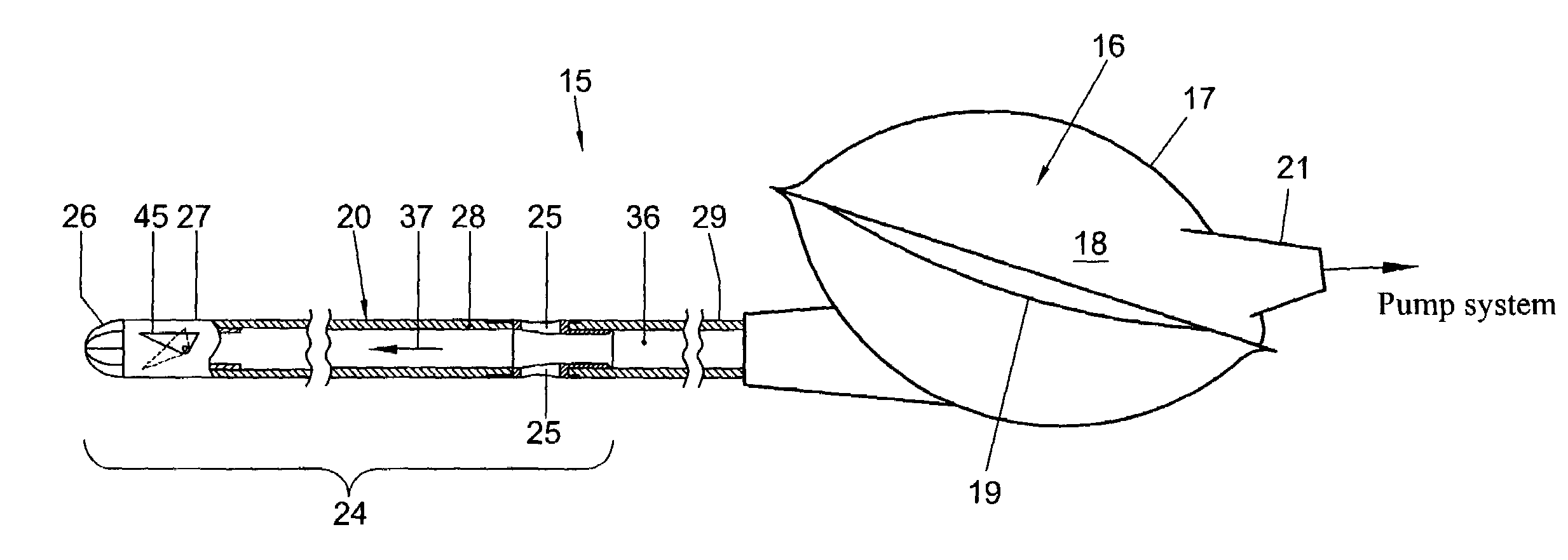
[0009]It is an object of the present invention to provide a simple and reliable catheter pump of the type in which blood is alternatingly displaced towards and away from a proximal displacement structure and, generally, moves from an inlet spaced from the tip to a more distal outlet, in which the risk of blood damage and thrombosis is at least reduced.
[0021]In spite of the inlet passage or passages being continuously open, when the displacement device alternatingly urges blood through the channel in distal and proximal direction, over a complete cycle, a net displacement of blood from the inlet through the channel to the outlet is obtained. If any, the volume of blood that is pushed back through the inlet opening or openings when the displacement device displaces blood in distal direction is smaller than the volume of blood that enters the channel via the inlet opening or openings when blood is pulled through the catheter channel in proximal direction. This effect is achieved because during flow in distal direction, blood reaches the inlet passages as a flow having a direction determined by the direction in which the channel extends immediately proximally of the inlet passage or passages, i.e. the flow in distal direction has a substantial directional effect on the flow in the area of the inlet passage or passages. In contrast, the direction of the flow in proximal direction away from the inlet passage or passages has relatively little directional effect on the flow in the area of the inlet passage or passages. Therefore, in response to the withdrawal of blood from behind the inlet passage or passages, blood can flow into the channel via the inlet passage or passages in directions having a component transverse to the direction of the channel via the inlet relatively easily.
[0022]Since, in operation, the inlet passage or passages are continuously open, there is no need to provide valves at the inlet passage or passages. In turn, this allows a very simple construction and blood cell damage and risk of thrombosis as typically caused by valves are avoided.
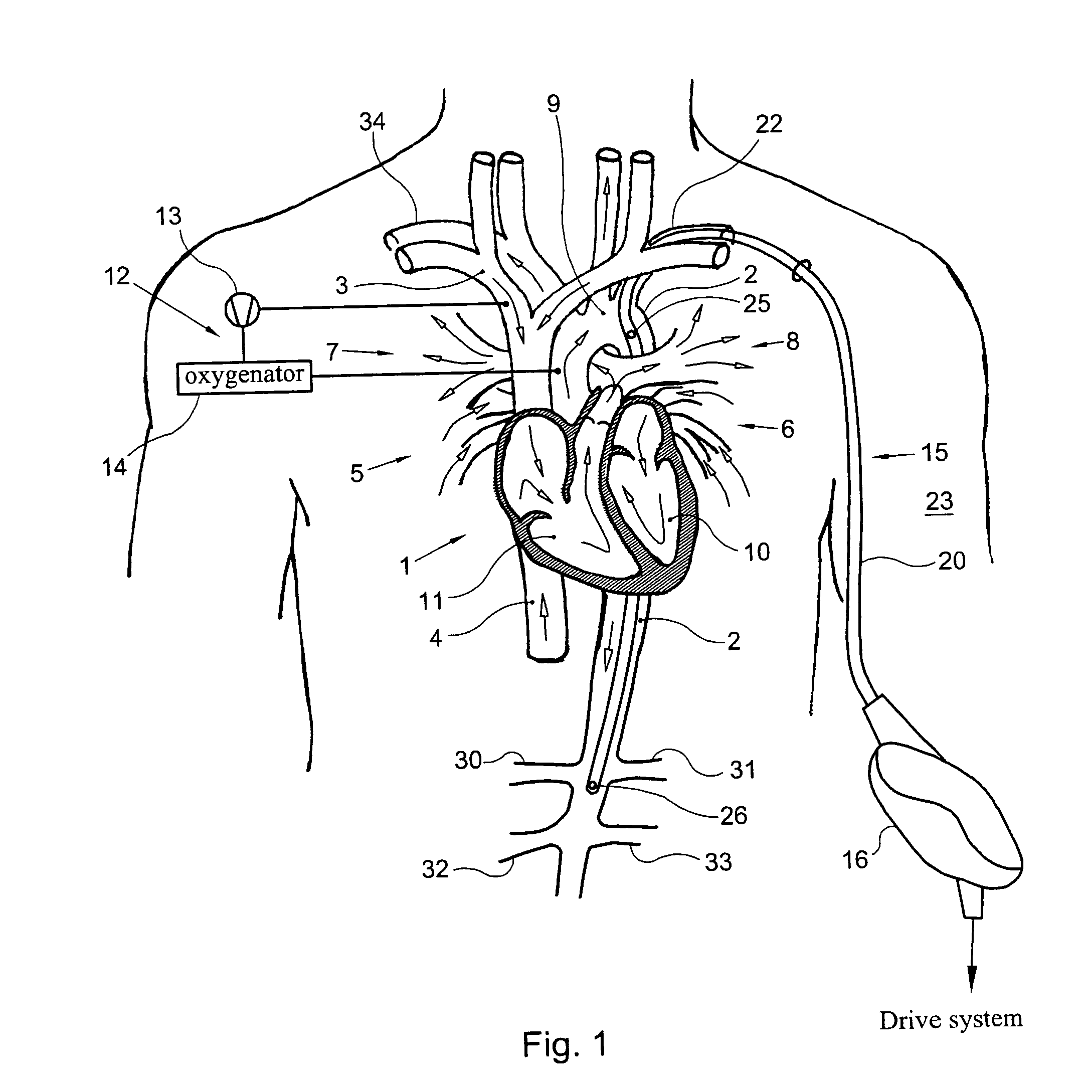
[0024]The catheter is thus arranged in the aorta with its distal end portion oriented in downstream direction with the fluid inlet located proximally of the fluid outlet. Withdrawing the fluid from an area upstream of the section of the aorta where the fluid is expelled from the catheter is relatively easy and the pulsatile outflow in the narrower section of the aorta is very effective for causing pulsatile pressure peaks of the blood pressure in a section of the aorta where the arteries towards the organs branch off from the aorta.

Problems solved by technology

An important problem associated with pumping blood is that blood cells are easily damaged in the valves, where the blood experiences abrupt changes in either the rate or direction of its flow under influence of mechanical forces and that, at the valves, the risk of thrombosis is increased.
However, these solutions are still relatively complex and specifically suitable for catheters in which blood is displaced away from the tip towards an outlet more spaced from the tip than the inlet.

Method used


Image

  • Catheter pump, catheter and fittings therefore and methods of using a catheter pump
  • Catheter pump, catheter and fittings therefore and methods of using a catheter pump
  • Catheter pump, catheter and fittings therefore and methods of using a catheter pump

Examples


Embodiment Construction

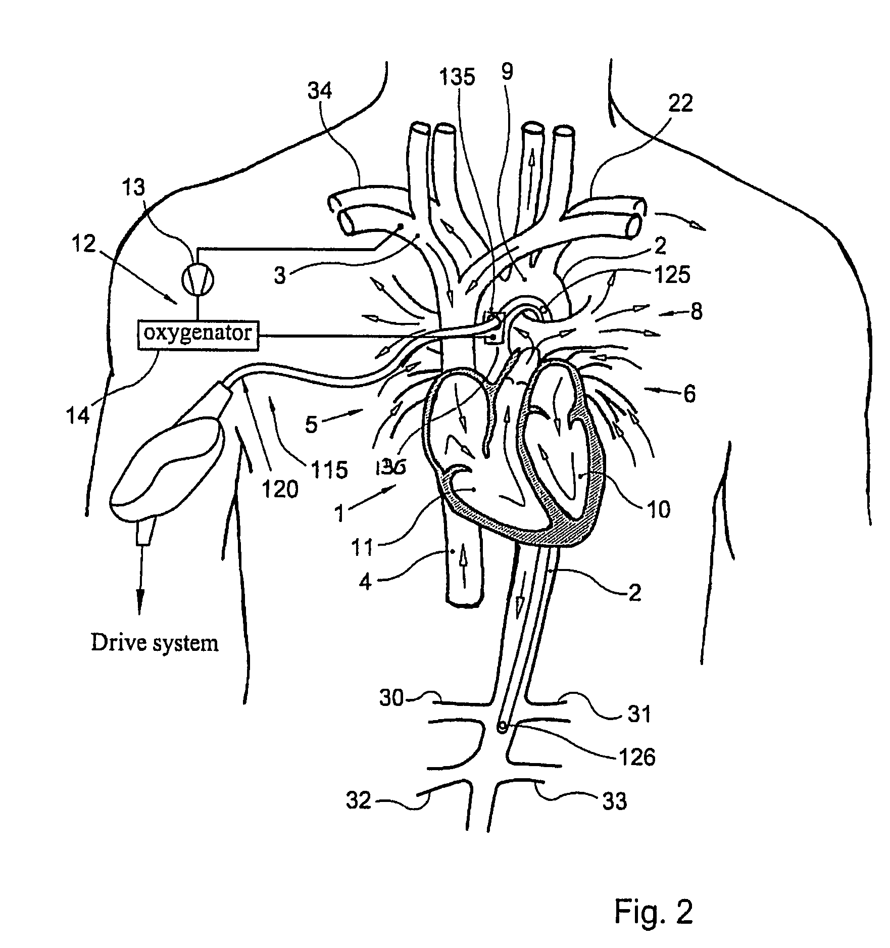
[0034]In FIG. 1 a human thorax is illustrated in a view showing the heart 1, the aorta 2, the superior vena cava 3, the inferior vena cava 4, the right pulmonary veins 5, the left pulmonary veins 6, right pulmonary arteries 7, the left pulmonary arteries 8, the aortic arch 9, the left ventricle 10 and the right ventricle 11. Arrows indicate blood flow directions when the heart 1 is in operation. During open-heart surgery on an inactive heart 1, in practice, blood circulation is usually maintained using a heart lung machine 12 (shown schematically only) including a pump 13 and an oxygenator 14. The heart lung machine is connected to the human body for pumping blood from the vena cava 3 to the aorta 2 and maintains the blood circulation in the patient. The blood flow from the heart lung machine 13 to the patient is essentially non-pulsatile. This essentially non-pulsatile blood flow enters the aorta 2 closely adjacent the heart 1, which has been deactivated. The pump 13 is a non-pulsa...


PUM


Abstract

A catheter pump includes a catheter channel communicating with a distal end portion of the catheter for alternatingly leading fluid in proximal and distal directions. At least one outlet passage is distally spaced from the inlet passage or passages. The catheter pump further includes a displacement structure communicating with the proximal end portion of the catheter for alternatingly applying suction and pressure for driving the fluid displacement. At least in operating condition, the inlet passage or passages are continuously open. A catheter and fittings for such a catheter pump and method of using a catheter pump are also described.

Description

[0001]This application claims the benefit of U.S. Provisional Patent Application Ser. No. 60 / 499,488 filed on Sep. 2, 2003.TECHNICAL FIELD[0002]The invention relates to a catheter pump, to a catheter, to fittings therefore and to a method of using a catheter pump.BACKGROUND ART[0003]From U.K. patent specification 1,370,546 a heart assist catheter pump is known which includes a catheter having a distal end for insertion from the aorta past the aortic valve into the left ventricle. The distal end has inlet openings. Spaced from the distal end, the catheter has outlet openings and a set of check valves for allowing outward flow. Valves are provided for controlling the direction of the flow. A fluid displacement device communicating with the proximal end of the catheter alternatingly generates a suction causing blood to be withdrawn from the left ventricle into the catheter and to the displacement device and an excess pressure causing blood to be expelled from the catheter downstream si...

Claims


Application Information

Patent Timeline
Patent Type & Authority Patents(United States)
IPC IPC(8): A61M25/14A61M25/00A61M60/113A61M60/178A61M60/268A61M60/38A61M60/894
CPCA61M1/107A61M1/1039A61M1/122A61M25/0043A61M60/113A61M60/279A61M60/274A61M60/894A61M60/148A61M60/38A61M60/178
Inventor RAKHORST, GERHARDVAN LOON, JAN-PAULVAN DER BOM, MARTIJN JOHN
Owner PLUSECATH BV
Learn More