Magneto resistive (MR) head

a magneto resistive and head technology, applied in the field of magneto resistive (mr) head, can solve the problems of mr head damage, mr head damage, and mr head damage, and achieve the effect of facilitating the diffusion of static electricity

Inactive Publication Date: 2005-09-22
FUJIFILM HLDG CORP +1
View PDF5 Cites 13 Cited by
  • Summary
  • Abstract
  • Description
  • Claims
  • Application Information

AI Technical Summary

Benefits of technology

[0026] With the conductive boundary layer, static electricity is discharged through the conductive region, the boundary layer and the substrate. Hence, discharging of static electricity is further facilitated.

Problems solved by technology

MR heads, however, have a property of being sensitive to static electricity and heat, in comparison with conventional inductive heads.
As a result, the MR head may be damaged due to the electro-static discharge (ESD).
Even in this MR head, however, static electricity on a magnetic tape is not always discharged sufficiently through the substrate and the protective substrate, and the static electricity may be discharged through the MR element or charge an insulating layer formed near the MR element.
In this case, the MR element is possibly damaged.

Method used


Image

  • Magneto resistive (MR) head
  • Magneto resistive (MR) head
  • Magneto resistive (MR) head

Examples


first embodiment

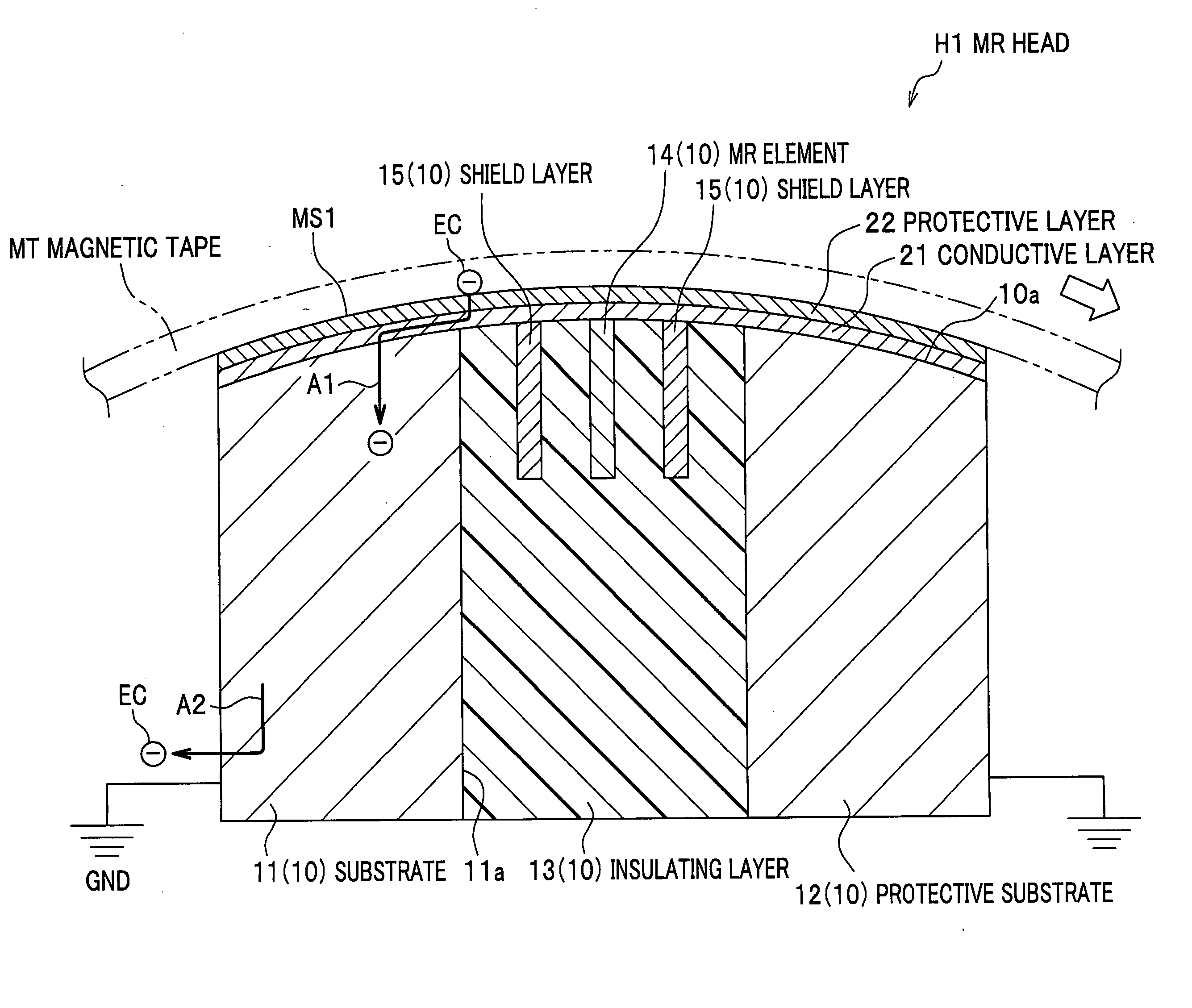
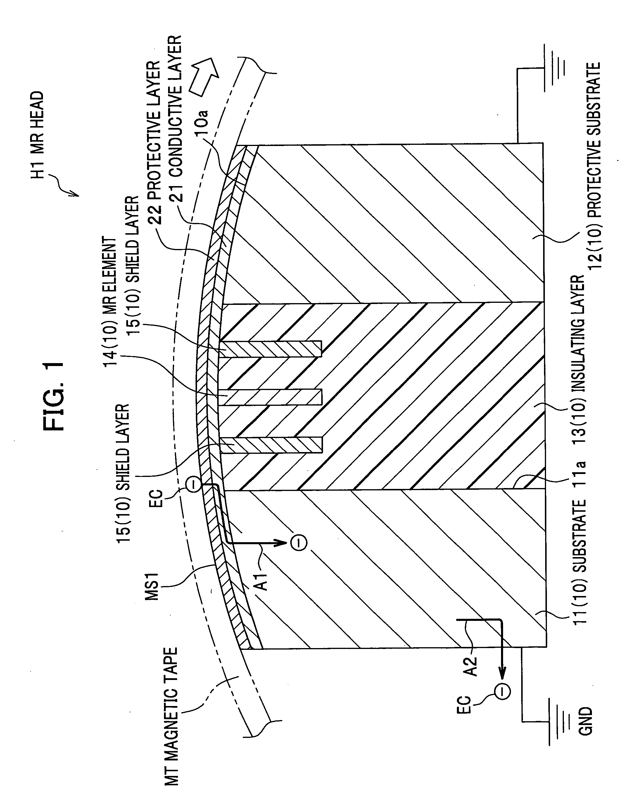
[0032] A description will be given below of a magneto resistive (MR) head according to a first embodiment of the present invention, with reference to FIG. 1.

[0033] Referring to FIG. 1, an MR head H1 includes, as main components, an MR head main body 10, a conductive layer 21 and a protective layer 22. Furthermore, the MR head main body 10 includes an MR element 14, shield layers 15 and 15, and an upper surface 10a which is located near a running magnetic tape MT, and where the MR element 14 and the shield layers 15 and 15 are partially exposed. The conductive layer 21 and the protective layer 22 are stacked on the upper surface 10a sequentially. The upper surface of the protective layer 22 serves as a magnetic tape contact surface MS1 to be in contact with the magnetic tape. zIn this embodiment, a description will be given, assuming that an MR head of the present invention is applied to the reproducing MR head H1. This MR head H1 uses an MR element 14 to read magnetic signals from ...

second embodiment

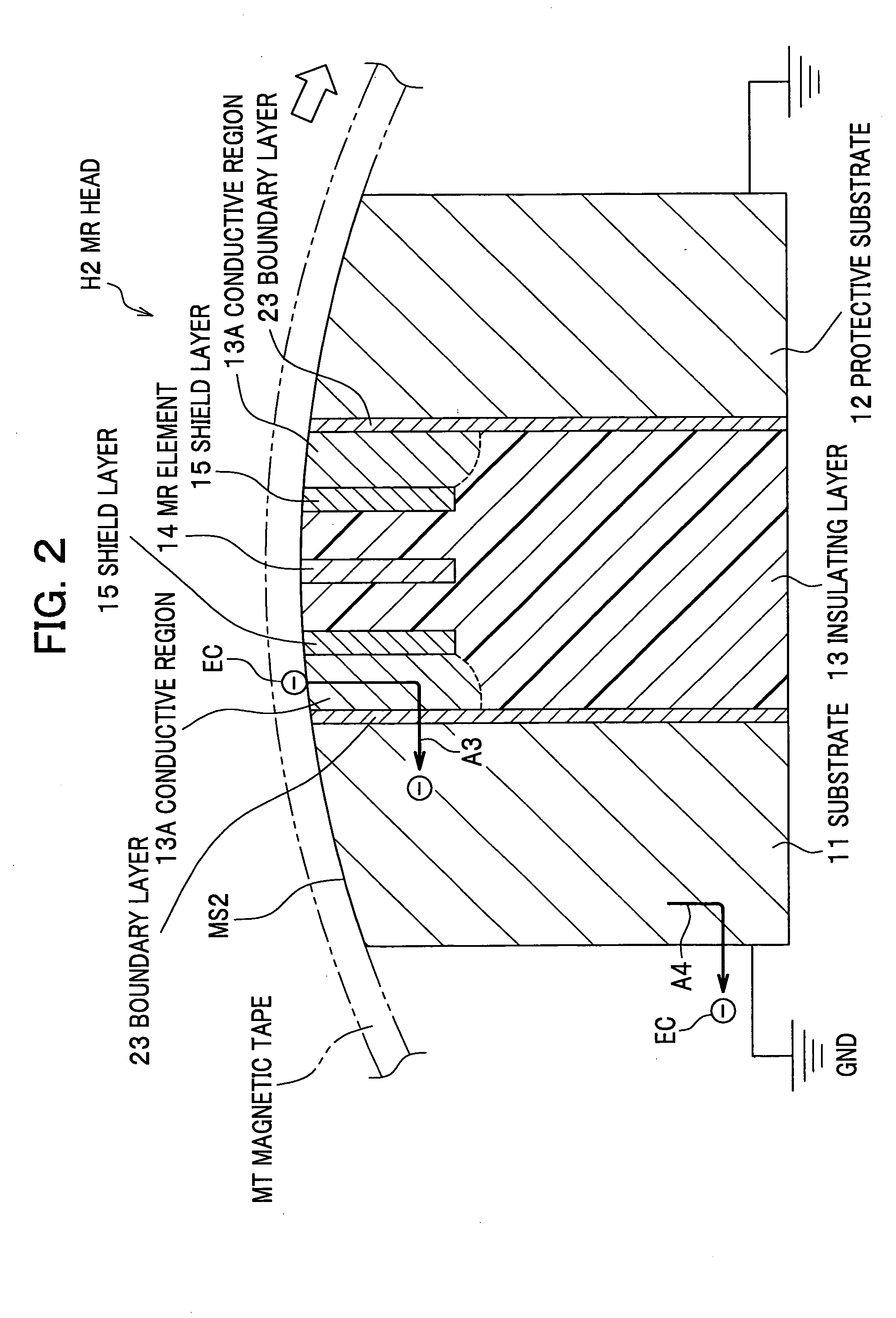
[0055] A description will be given below of an MR head according to a second embodiment of the present invention, with reference to FIG. 2.

[0056] Referring to FIG. 2, the MR head H2 according to the second embodiment is not provided with the conductive layer 21 and the protective layer 22 according to the first embodiment (see FIG. 1). Instead, the insulating layer 13 incorporates insulating conductive regions 13A each containing a high concentration of carbon (C). In addition, boundary layers 23 and 23 are formed on the respective sides of the insulating layer 13. The MR head H2 has a magnetic tape contact surface MS2 to be in contact with the magnetic tape MT.

[Conductive Region]

[0057] Each conductive region 13A is a region of high conductivity, and is formed by partially mixing carbon (C) into alumina (Al2O3), etc. making up the insulating layer 13. The conductive regions 13A are partially exposed from the upper surface of the magnetic tape contact surface MS2, and are electric...


PUM

PropertyMeasurementUnit
resistivityaaaaaaaaaa
thicknessaaaaaaaaaa
thicknessaaaaaaaaaa

Abstract

Disclosed is an MR head in which the MR element resists damage due to ESD. A magneto resistive head to be in contact with a running magnetic tape includes a substrate, an insulating layer, a magneto resistive element located in the insulating layer, at least one shield layer for shielding the magneto resistive element from magnetic fields, and a conductive layer that has a conductive surface being in contact with the magnetic tape and that is electrically connected to the substrate. In this head, static electricity accumulated on the magnetic tap is discharged through the conductive layer and the substrate.

Description

BACKGROUND OF THE INVENTION [0001] 1. Field of the Invention [0002] An apparatus consistent with the present invention relates to a magneto resistive (MR) head having a magneto resistive (MR) element.[0003] 2. Description of the Related Art [0004] Recently, the recording density of magnetic tapes has been increased. In order to follow this trend, magneto resistive (MR) heads have necessarily been used as heads for reading magnetic signals in tape drives (e.g. magnetic recording / reproducing apparatuses), instead of conventional inductive heads. An MR head has a magneto resistive (MR) element which possesses a high sensing sensitivity to magnetic signals and enables a high reproducing output. Therefore, use of an MR head makes it possible to narrow the recording tracks on a magnetic tape and to increase the line recording density of a magnetic tape, thereby realizing the high density recording and reproduction. [0005] MR heads, however, have a property of being sensitive to static ele...

Claims


Application Information

Patent Timeline
Patent Type & Authority Applications(United States)
IPC IPC(8): G11B5/39G11B5/127G11B5/33
CPCG11B5/39G11B5/1272
Inventor SUDA, TAKASHI
Owner FUJIFILM HLDG CORP
Why Eureka
Try Eureka