Eureka AIR delivers breakthrough ideas for toughest innovation challenges, trusted by R&D personnel around the world.

Single panel golf club grip

Inactive Publication Date: 2005-09-22
WINN INC
View PDF99 Cites 9 Cited by
  • Summary
  • Abstract
  • Description
  • Claims
  • Application Information

AI Technical Summary

Benefits of technology

[0007] In one embodiment, the golf club grip overcomes the aforementioned disadvantages of existing spirally wrapped grips while providing the same resistance to shock afforded by such grips, as well as providing tackiness and reducing the overall weight of the grip. An embodiment consists of a grip for a golf club comprising a resilient underlisting sleeve having a main portion, a top end, and a bottom end. The sleeve further comprises a cap positioned at the top end which defines an underside portion positioned between the end of the cap and the bottom end of the sleeve. The sleeve also comprises a hole configured to receive the end of a golf club shaft and positioned near the bottom end of the sleeve. The grip further comprises a single panel comprising a top region having skiving along the length of the region, a bottom region, and two side regions. The panel further comprises a configuration corresponding to the exterior shape of the resilient sleeve and an inner layer and an outermost layer, the inner layer comprising one of a fabric and a polymer. The panel is adhered to the underlisting sleeve such that the outermost layer in the top region contacts the underside portion of the cap.
[0009] The golf club grip may be manufactured at considerably less cost than existing spirally wrapped grips, since the intensive labor of spirally wrapping a strip around an underlisting sleeve within specific pressure parameters is eliminated. Additionally, the single panel grip will desirably not twist either during manufacture or after it is adhered to an underlisting sleeve. My new grip desirably has an appearance similar to conventional molded rubber grips so as to appeal to professional golfers and low-handicap amateurs, and desirably also provides a greater area for the application of decorative designs.

Problems solved by technology

While such grips have proven satisfactory in reducing impact shock, their fabrication is labor intensive, particularly since the strip must be wrapped manually about the underlisting sleeve within specific pressure parameters.
Additionally, it is difficult to accurately align the adjoining side edges of the strip as such strip is being spirally wrapped about underlisting sleeve.
This is a particularly difficult problem when wrapping putter grips.
These wrapped grips also do not lend themselves to the display of decorative designs.

Method used


Image

  • Single panel golf club grip
  • Single panel golf club grip
  • Single panel golf club grip

Examples


Embodiment Construction

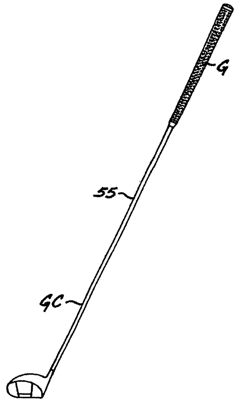
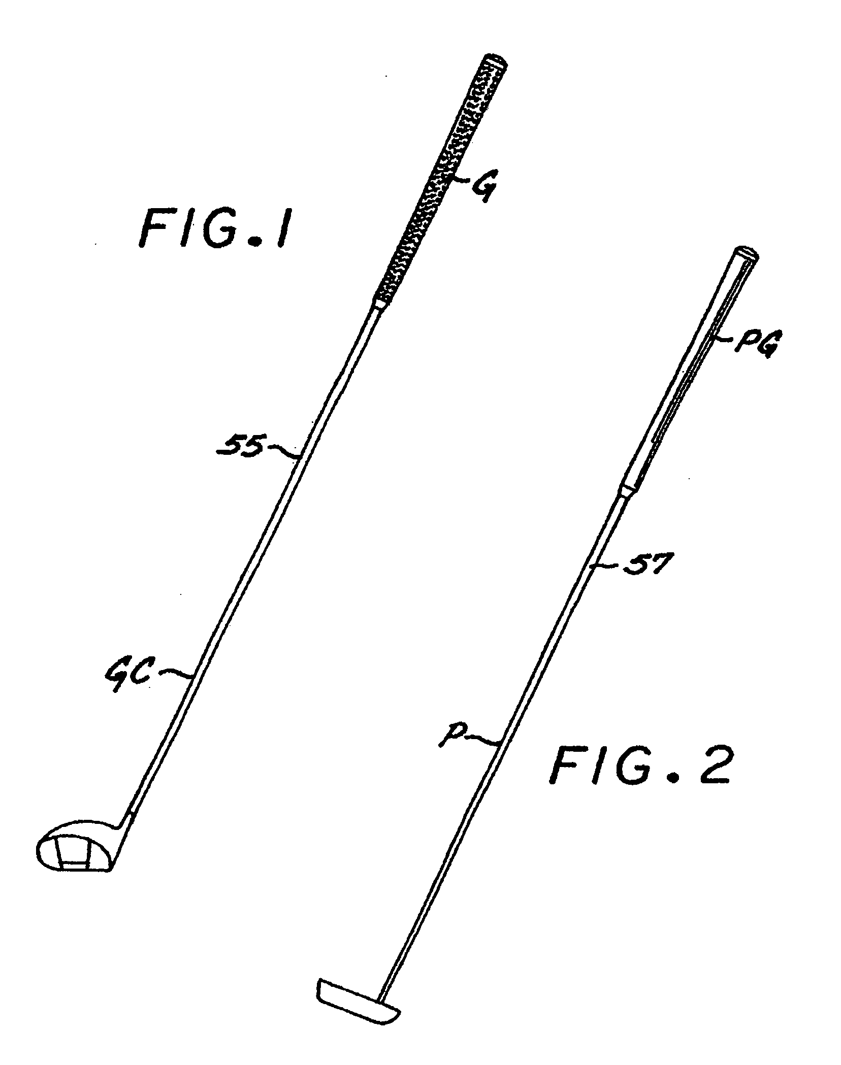
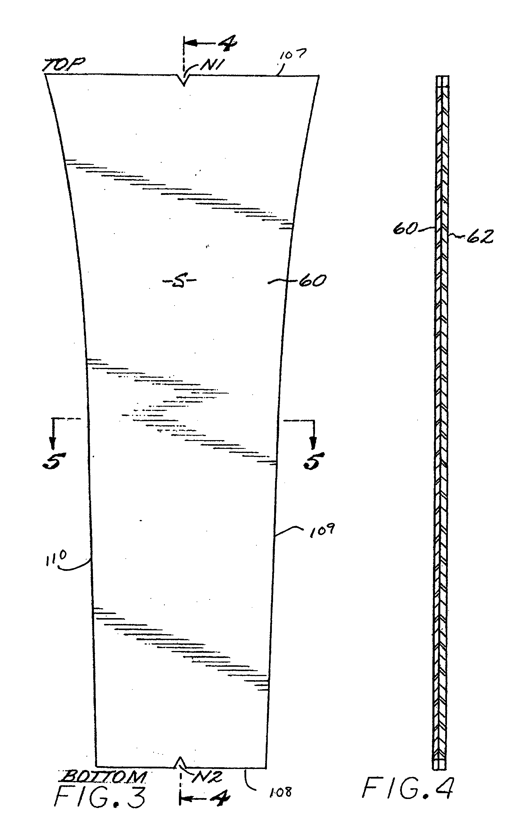
[0088] Referring to the drawings, in FIG. 1, a single panel grip G of one embodiment of the present invention is shown attached to the shaft 55 of a golf club GC. In FIG. 2, a single panel putter grip PG is shown attached to the shaft 57 of a putter P. Referring now to the remaining drawings, a preferred form of grip G includes a single panel S formed of a bonded-together outside or polymeric, preferably polyurethane, layer 60 and an inside or polymeric, preferably ethylene-vinyl acetate copolymer (EVA), layer 62, which is wrapped about and adhered to a resilient underlisting sleeve U of conventional construction.

[0089] The outside layer 60 of the single panel in this disclosure is generally referred to as a polyurethane layer. Though polyurethane is the preferred material, other materials could be used and achieve some advantages. In particular, other polymeric compounds can be used to create the outer layer and achieve some advantages. Similarly, the inside layer 62 is generally ...


PUM


Abstract

A grip for the handle of a golf club having a single panel that is wrapped about an underlisting sleeve comprising a cap. The panel further comprises an inner layer and an outermost layer, the inner layer comprising one of a fabric and a polymer. The panel is adhered to the underlisting sleeve such that the outermost layer in the top region contacts the underside portion of the cap. The unitary grip reduces impact shock and also provides a feeling of tackiness in the manner of a spirally wrapped grip.

Description

RELATED U.S. APPLICATION DATA [0001] This application is a continuation of U.S. patent application Ser. No. 10 / 875,035, Filed Jun. 23, 2004, pending, which is a continuation-in-part of U.S. patent application Ser. No. 10 / 392,480, filed Mar. 18, 2003, now U.S. Pat. No. 6,857,971, and a continuation-in-part of U.S. patent application Ser. No. 10 / 746,764, filed Dec. 23, 2003, now U.S. Pat. No. 6,843,732, and claims the benefit of U.S. Provisional Application No. 60 / 572,604, filed May 19, 2004. This application is also a continuation-in-part of U.S. patent application Ser. No. 11 / 062,046, filed Feb. 18, 2005, pending, which is a continuation of U.S. patent application Ser. No. 10 / 392,480, filed Mar. 18, 2003, now U.S. Pat. No. 6,857,971. This application is also a continuation-in-part of U.S. patent application Ser. No. 11 / 029,328, filed Jan. 5, 2005, pending, which is a continuation of U.S. patent application Ser. No. 10 / 746,764, filed Dec. 23, 2003, now U.S. Pat. No. 6,843,732. This a...

Claims


Application Information

Patent Timeline
IPC IPC(8): A63B53/14A63B59/00
CPCA63B53/14A63B59/0014Y10T156/10Y10T156/1052A63B59/0092A63B60/06A63B60/08A63B60/10A63B60/54A63B60/14
Inventor HUANG, BEN
Owner WINN INC
Why Eureka
Eureka Blog
Learn More