
Systems and methods for mixing fluids

Inactive Publication Date: 2005-09-22
SPINEWAVE
View PDF10 Cites 117 Cited by
  • Summary
  • Abstract
  • Description
  • Claims
  • Application Information

AI Technical Summary

Benefits of technology

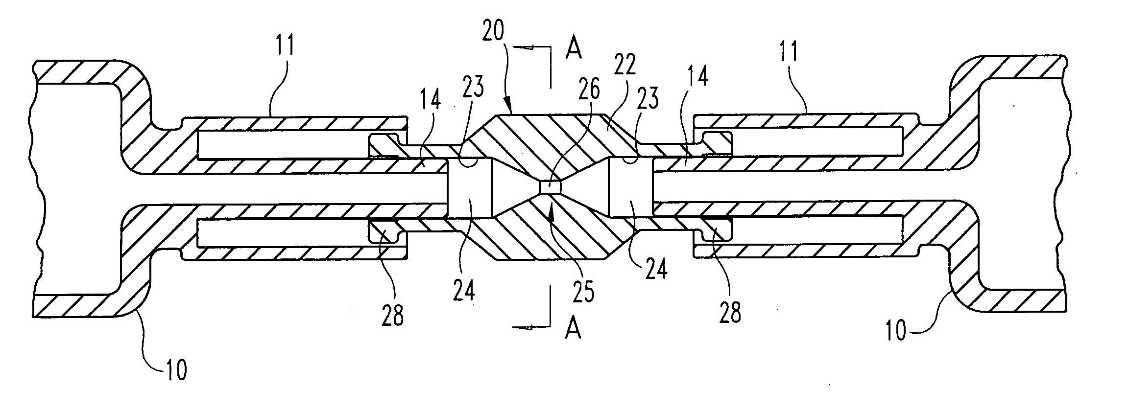
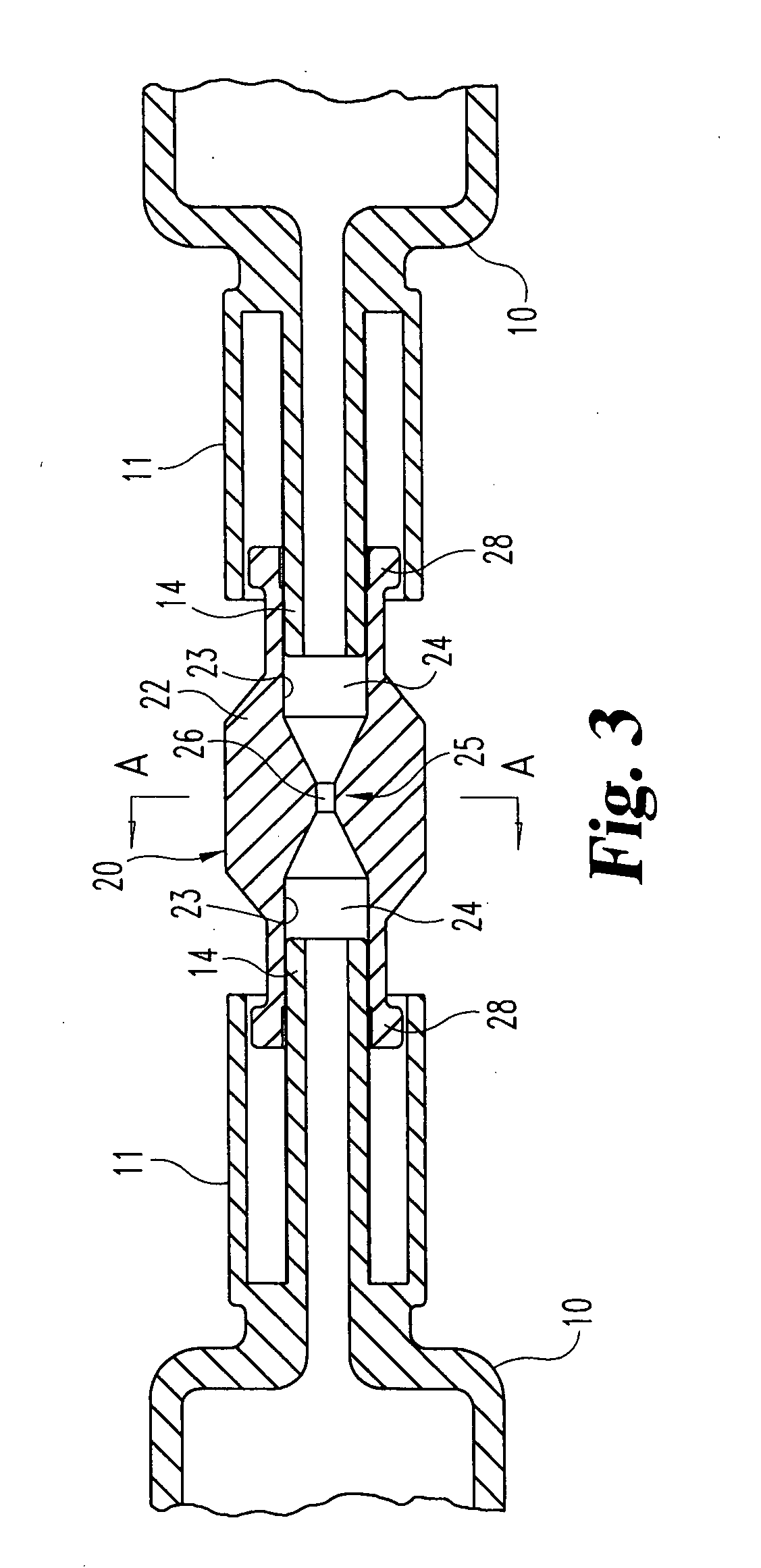
[0028] In one embodiment, this means for modifying the flow of fluid can include an elongated body, adapted at its ends to engage a corresponding one of the two syringes. The elongated body defines a fluid passageway in communication with the two syringes and a restriction within the passageway. The restriction can be in the form of a nozzle adapted to significantly increase the fluid flow velocity through the apparatus.
[0030] It is one object of the present invention to provide a syringe-to-syringe mixing system that efficiently mixes at least two constituents of a fluid composition. It is one particular object to provide a mixing system that can quickly and thoroughly mix the constituents of a composition that is “time sensitive”, such as compositions that begin curing when mixed.
[0032] One benefit of the mixing apparatus of the present invention is that it can be used with traditional syringe-to-syringe mixing systems. Another benefit is that it provides complete and rapid mixing with minimal effort on the part of medical personnel. A further benefit of the present invention is that it is ideally suited for mixing self-curing compositions, or compositions that begin curing once the constituents come in contact with each other in appropriate ratios.

Problems solved by technology

These systems are generally not adequate for mixing polymers with high mix ratios.
A further drawback is that a considerable amount of material is wasted in the mix tip, which may not be problematic for low cost fluid compounds but is potentially prohibitive for expensive materials, such as an injectable disc nucleus material.
Continuous flow systems are best suited for “assembly line” production and are excessive and too expensive for mixing single batches of fluid compounds.
One drawback of these prior systems is that they require relatively high plunger forces when mixing viscous fluids, which can lead to user fatigue.
Another problem is that it is time consuming to achieve uniform distribution of micro-droplets within a fluid mixture.
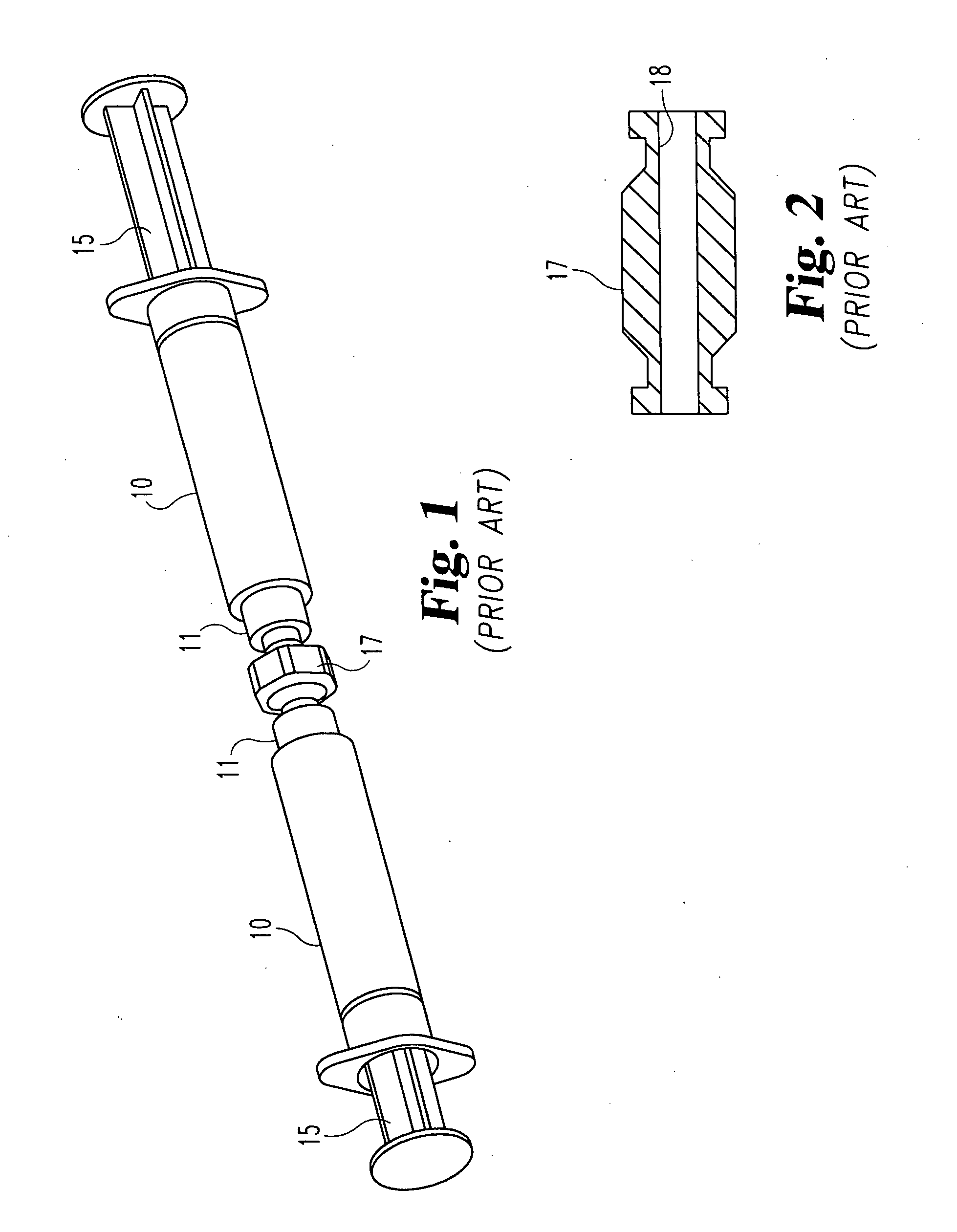
Furthermore, in certain medical applications, the degree of mixing that can be accomplished with prior adapters, such as the adapter 17, is less than optimum.
This problem manifests itself where high mix ratios are involved.
This mixing problem is also critical where the fluids combine to form a curable composition.
However, the time necessary to achieve complete mixing is prohibitive for some curable materials that cure relatively quickly.
If these types of materials are not dispensed in a timely manner, the mixture is worthless.

Method used


Image

  • Systems and methods for mixing fluids
  • Systems and methods for mixing fluids
  • Systems and methods for mixing fluids

Examples


Embodiment Construction

[0053] For the purposes of promoting an understanding of the principles of the invention, reference will now be made to the embodiments illustrated in the drawings and described in the following written specification. It is understood that no limitation to the scope of the invention is thereby intended. It is further understood that the present invention includes any alterations and modifications to the illustrated embodiments and includes further applications of the principles of the invention as would normally occur to one skilled in the art to which this invention pertains.

[0054] The present invention contemplates a mixing apparatus for use with a pair of syringes, such as the syringes 10 shown in FIG. 1. The mixing apparatus can be configured to mate with any syringes, such as by a press-fit engagement with the syringe tip, by Luer connection or other suitable means. As shown in FIG. 3, the syringe 10 can include a Luer fitting 11 with a fluid dispensing tip 14 extending concen...


PUM


Abstract

Improvements are provided for a syringe-to-syringe mixing system to improve the mixing characteristics of the system. In one embodiment, a mixing apparatus includes opposite fittings for mounting to a pair of syringes. The mixing apparatus defines a fluid passageway therethrough and includes a flow modifying element disposed within the passageway. The flow modifying element is configured to increase the flow velocity, disrupt the fluid flow or introduce turbulence into the fluid flow between the two syringes. In another embodiment, a nozzle element is disposed within the tip of the syringe, the element configured to increase the fluid flow therethrough. The nozzle element can be a nozzle insert removably mounted within the tip, or an integrally formed nozzle within the tip.

Description

BACKGROUND OF THE INVENTION [0001] This invention relates to systems and methods for mixing fluids, and particularly medical fluids. More specifically, the invention relates to improvements in syringe-to-syringe mixing systems. [0002] Several systems have been developed for on-site mixing and dispensing of multi-part medical and dental compositions. One system uses dual-cartridge syringes with static mix tips. These systems are generally not adequate for mixing polymers with high mix ratios. A further drawback is that a considerable amount of material is wasted in the mix tip, which may not be problematic for low cost fluid compounds but is potentially prohibitive for expensive materials, such as an injectable disc nucleus material. [0003] Another known system, known as continuous flow systems, uses an electromechanical apparatus that drives a mix tip for controlled mixing of the fluids. Continuous flow systems are best suited for “assembly line” production and are excessive and too...

Claims


Application Information

Patent Timeline
IPC IPC(8): A61J1/00A61J1/20A61M5/178A61M5/31A61M37/00
CPCA61J1/2089A61J1/2096A61J2001/201A61M5/3134A61J2001/2055A61J2001/2058A61M5/1782A61J2001/2044A61J1/201A61J1/2044A61J1/2055A61J1/2058
Inventor MIDDLETON, LANCEREED, SCOTTWALKENHORST, JARED
Owner SPINEWAVE
Learn More