Hydraulic actuator having disc valve assembly

a technology of disc valve and actuator, which is applied in the direction of spring/damper, shock absorber, servomotor, etc., can solve the problems of disc material fatigue limit, valve failure to close, and stress that exceeds the yield strength of disc material, so as to reduce stress build-up and prolong the useful life

Active Publication Date: 2005-09-29
DELPHI TECH INC +1
View PDF7 Cites 26 Cited by
  • Summary
  • Abstract
  • Description
  • Claims
  • Application Information

AI Technical Summary

Benefits of technology

[0006] In accordance with this invention, a hydraulic actuator comprises a housing, a piston reciprocal within the housing and dividing the interior thereof into a piston chamber and a rod chamber, and a rod connected to said piston and extending through the rod chamber. The piston comprising a passage having an opening to allow hydraulic fluid flow between the piston chamber to the rod chamber. The hydraulic actuator further comprises a disc valve assembly to open and close the passage. The disc valve assembly includes a washer mounted to the piston overlying the opening, spaced apart therefrom. A valve pack is mounted to the rod between the washer and the piston and includes at least one disc valve and preferably at least two disc valves, each having a flexible portion remote from the extension. Still further, the disc valve assembly includes a spacer arrangement that spaces the flexible portion of the disc valve apart from the washer. The spacer arrangement includes a first support point supporting the valve pack relative to the washer and at least one second support point spaced apart from the flexible portion of the disc valve when the valve pack is in an unflexed position. During operation, the valve pack flexes between a valve closed position and a valve open position. In the closed position, the valve pack closes the opening to prevent hydraulic fluid flow from the rod chamber to the piston chamber. In the open position, the flexible portion of the valve disc engages the washer to fully open the valve assembly to allow hydraulic fluid flow from the piston chamber to the rod chamber. In accordance with this invention, when the flexible portion flexes to the open position, the valve disc engages the second support point. This reduces stress build-up within the valve pack, particularly stresses that might otherwise be concentrated about the first support point, and thereby extends the useful life of the valve disc assembly and thus the hydraulic actuator.

Problems solved by technology

Circumstances may arise where the fluid pressure to open the valve may create stresses that exceed the yield strength of the disc material and deform the disc.
Moreover, repeated flexure may exceed the fatigue limit of the disc material.
As a result, the valve may fail to close, interfering with the proper operation of the hydraulic actuator.

Method used


Image

  • Hydraulic actuator having disc valve assembly
  • Hydraulic actuator having disc valve assembly
  • Hydraulic actuator having disc valve assembly

Examples


Embodiment Construction

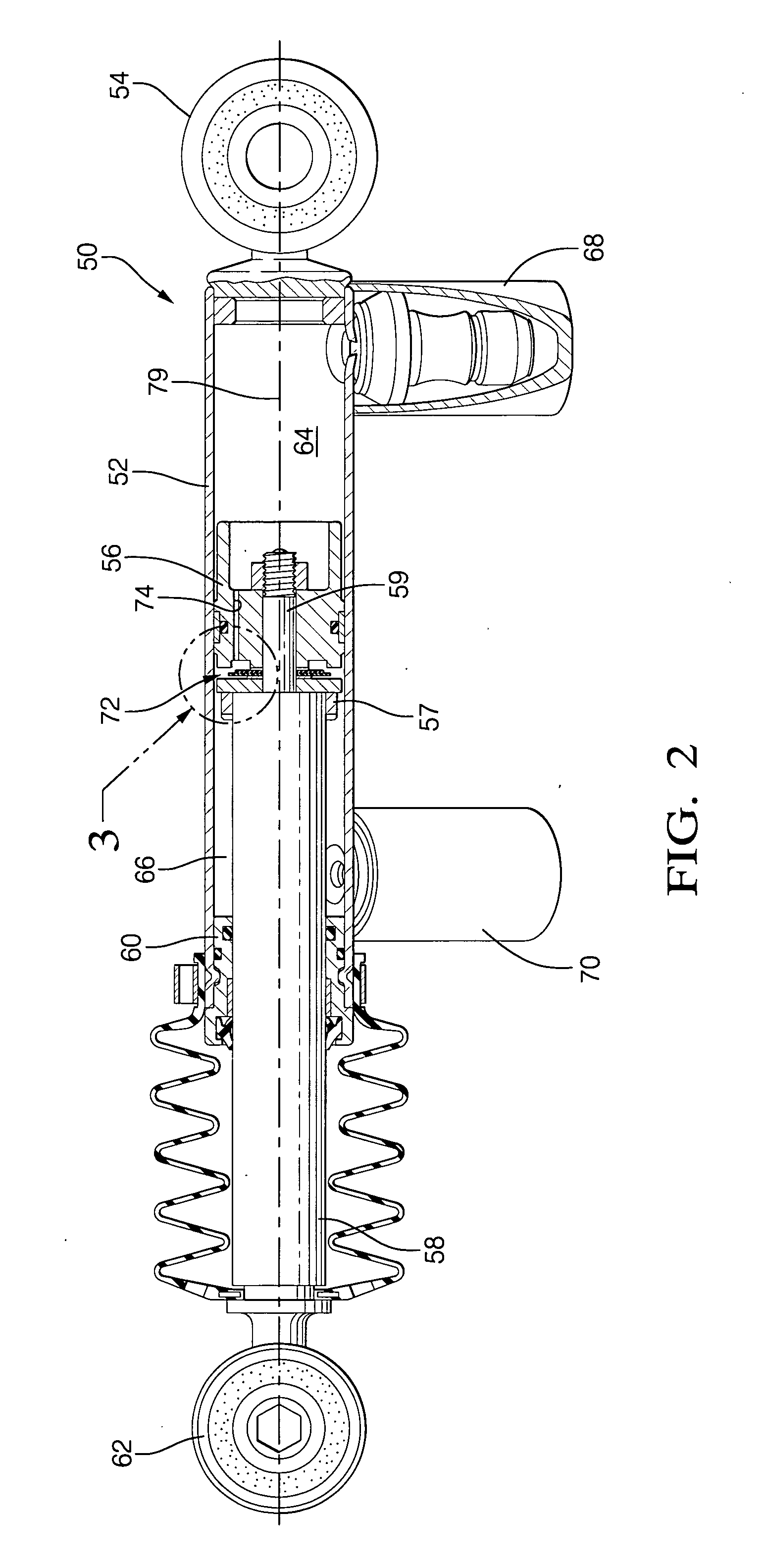
[0012] In accordance with a preferred embodiment of this invention, referring to FIG. 2, a hydraulic actuator 50 comprises a tubular housing 52 having a mounting bracket 54 at one end. A rod 58 extends through a seal 60 in the opposite end of housing 52 and includes a mounting bracket 62 at the external end thereof. A piston 56 is reciprocally mounted within the housing and is connected to a tenon or extension 59 on rod 58. Piston 56 divides the interior of housing 52 into a first chamber 64, referred to as the piston chamber, and a second chamber 66, referred to as the rod chamber. Actuator 50 includes fitting 68 for connecting the piston chamber to a reservoir and a pump (not shown) for pumping hydraulic fluid into and out of the piston chamber, and fitting 70 connecting to the rod chamber for pumping hydraulic fluid into and out of the rod chamber. A polymeric rebound bumper 57 is disposed about rod 58 to provide cushioning in the event of maximum extension of the rod. It is appr...


PUM


Abstract

A hydraulic actuator comprises piston that divides the interior into a piston chamber and a rod chamber and a valve disc assembly to regulate flow of hydraulic fluid between the piston chamber and the rod chamber through a passage in the piston. The disc valve assembly includes a washer, a valve pack that includes at least one flexible disc valve, and a spacer arrangement spacing the valve pack apart from the washer. During operation, the valve pack flexes to open and close the passage. The spacer arrangement includes a first support point supporting the valve pack relative to the washer and at least one second support point spaced apart from the flexible portion of the disc valve pack. In the open position, the valve pack engages the second support point to reduce stress build-up at the first support point, thereby reducing work fatigue of the valve disc and extending the useful life of the hydraulic actuator.

Description

CROSS REFERENCE TO RELATED APPLICATION [0001] This application claims the benefit of U.S. Provisional Application No. 60 / 555,784, filed Mar. 24, 2003, which is incorporated herein by reference.TECHNICAL FIELD OF INVENTION [0002] This invention relates generally to hydraulic actuators, and more particularly to a to hydraulic actuator that includes a disc valve assembly. BACKGROUND OF INVENTION [0003] A hydraulic mount for a vehicle comprises a tubular housing having a mounting bracket at one end, a piston disposed in the housing, and a rod connected to the piston and extending through a seal at the other end of the housing. The piston divides the housing into a piston chamber and a rod chamber. The rod includes a second mounting bracket at the end outside the housing. Hydraulic fluid is pumped into and out of the chambers to move the piston relative to the housing and thereby adjust the distance between the mounting brackets. The hydraulic actuator is installed by attaching the mount...

Claims


Application Information

Patent Timeline
Patent Type & Authority Applications(United States)
IPC IPC(8): F15B11/08F15B15/20F16F9/348
CPCF16F9/3485F15B15/204
Inventor DOURSON, STEPHEN E.STACEY, SCOTT A.PICHON, VINCENT G.
Owner DELPHI TECH INC
Why Eureka
Try Eureka