Composite hose with a corrugated metal tube and method for making the same

a technology of corrugated metal and composite hoses, which is applied in the direction of flexible pipes, hose connections, mechanical equipment, etc., can solve the problems of fatigue crack, fatigue crack of corrugated metal tubes, lowered durability, etc., and achieves the effect of reliable restraining effect, easy fatigue-broken, and reduced non-uniform durability of composite hoses

Inactive Publication Date: 2005-09-29
SUMITOMO RIKO CO LTD
View PDF19 Cites 19 Cited by
  • Summary
  • Abstract
  • Description
  • Claims
  • Application Information

AI Technical Summary

Benefits of technology

[0026] Also, according to the present invention, there is provided a new method for making a composite hose which has a corrugated metal tube in an inner peripheral portion. The method for making a composite hose comprises a first step of preparing a corrugated metal tube which includes a corrugated portion formed with corrugation hills and corrugation valleys, a second step of constructing an outer peripheral portion with flexibility on an outer periphery of the corrugated metal tube by forming an elastic layer on an outer periphery of the corrugated metal tube and providing a reinforcing layer on an outer periphery of the elastic layer, and a third step of plastically deforming the corrugated metal tube outwardly by exerting in an inside or the inner peripheral portion of the corrugated metal tube a deforming pressure beyond or exceeding a yield point of the corrugated metal tube. In the composite hose with a corrugated metal tube which is made or manufactured in this manner, even if the corrugated metal tube is subject to a pressure beyond a deforming pressure by an internal fluid in a use or service environment, restraining force of the reinforcing layer is immediately exerted to the corrugated metal tube, and thereby a fatigue crack is hardly caused. However, here, it is feared that the corrugated metal tube compresses the elastic layer and is slightly expanded. So, in order to obtain more reliable restraining effect from the reinforcing layer, deforming pressure to be exerted to an inside of the corrugated metal tube is preferably set higher than a pressure to be exerted by an internal fluid in a use or service environment.
[0027] The present invention relates, for example, to a composite hose with a corrugated metal tube as a barrier layer against permeation of conveyed fluid, which is preferably usable for conveying fuel in automobiles, conveying refrigerant, conveying fuel of cell such as hydrogen gas used in a fuel cell or other applications. And, a corrugated shape or a performance based on the shape provides a corrugated metal tube with an effect of flexibility. A material of the corrugated metal tube itself is a metal and does not have elasticity different from rubber or the like. So, such composite hose with a corrugated metal tube involves a problem that the composite hose with a corrugated metal tube is deformed repeatedly during active use resulting that the corrugated metal tube is readily fatigue-broken.
[0028] In the composite hose according to the present invention or the composite hose made in the method according to the present invention, there occurs no damage such as bursting even if used for a long term in the environment where high pressure is exerted repeatedly by an internal fluid. Further, the method for making a composite hose according to the present invention provides an advantage to reduce nonuniformity of durability of the composite hoses as restraining functions are kept uniform when the corrugated metal tubes are plastically deformed even if the reinforcing layers have nonuniform restraining functions.

Problems solved by technology

By the way, after the inventors precisely investigated fatigue crack of the corrugated metal tube, it is found out that repeated internal pressures tend to cause a crack on the tops of the corrugation hills resulting in a fatigue crack of the corrugated metal tube, while repeated bending deformations based on flexibility of the corrugated metal tube tends to cause a crack in bottoms of the corrugation valleys resulting in a fatigue crack of the corrugated metal tube.
In some cases, lowered durability against repeated bendings causes inconvenience.

Method used


Image

  • Composite hose with a corrugated metal tube and method for making the same
  • Composite hose with a corrugated metal tube and method for making the same
  • Composite hose with a corrugated metal tube and method for making the same

Examples


Embodiment Construction

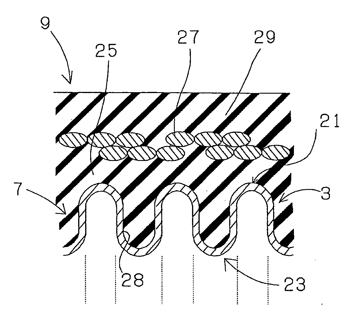
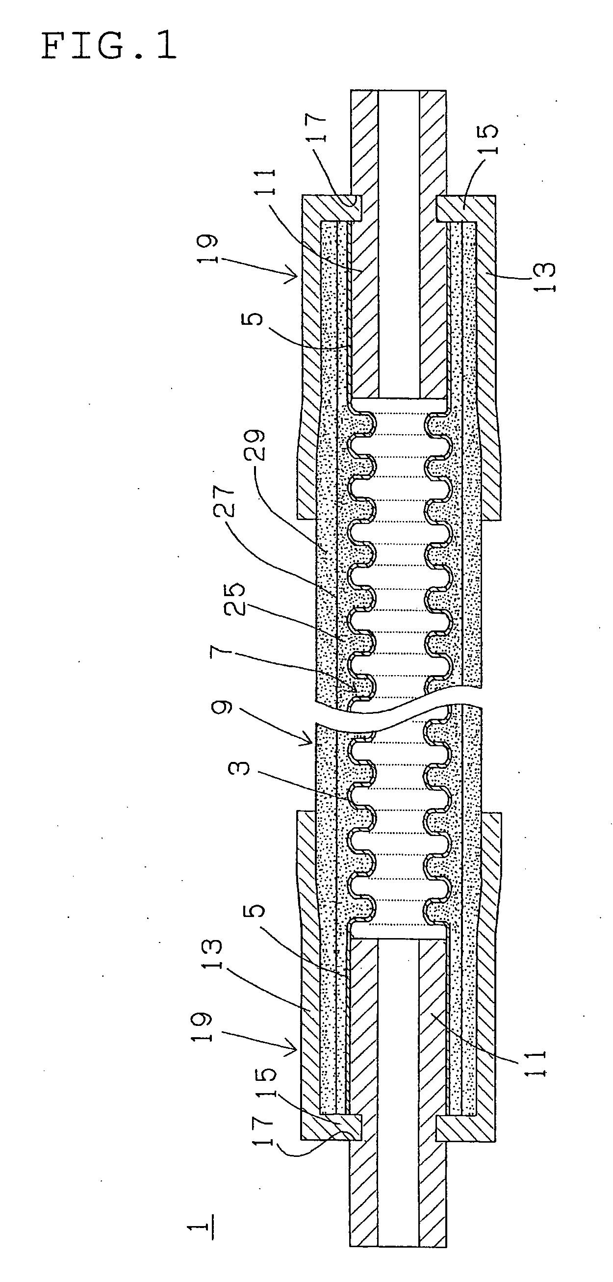
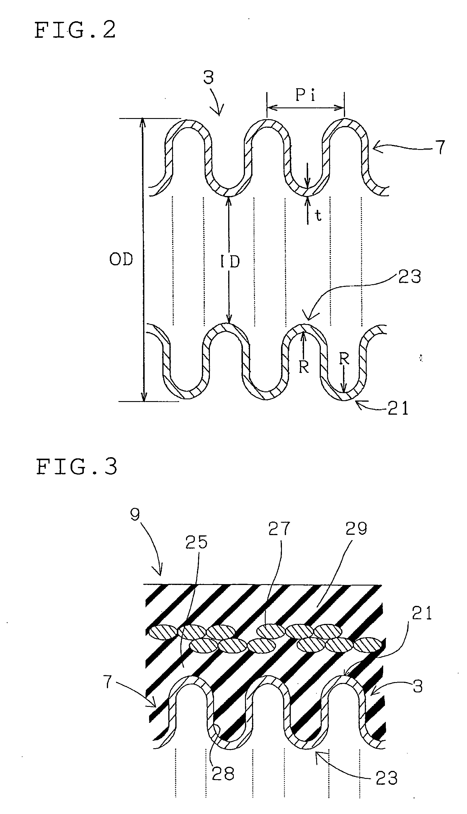
[0044]FIG. 1 shows a first composite hose with a corrugated metal tube (wherein a corrugate metal tube is not plastically deformed yet) according to the present invention. A first composite hose with a corrugated metal tube 1 (hereinafter referred to just as a first hose 1) comprises a corrugated metal tube 7 as an inner peripheral portion, an outer peripheral portion 9 which is provided on an outer side of the corrugated metal tube 7, a metal insert fitting 11 which is shaped a pipe. The corrugated metal tube 7 integrally has a corrugated portion 3 which is formed with corrugation hills and corrugation valleys and straight-wall portions 5, 5 which are formed on opposite ends of the corrugated portion 3. The insert fitting 11 is inserted in each of the straight-wall portions 5, 5 of the corrugated metal tube 7. The first hose 1 further comprises sleeve-like socket fittings 19, 19. Each socket fitting 19 integrally has a tubular portion 13 and an inwardly-directed flange 15 which is ...


PUM


Abstract

A composite hose is constructed to have an outer peripheral portion and an inner peripheral portion. The outer peripheral portion includes an elastic layer and a reinforcing layer provided on an outer periphery of the elastic layer. The inner peripheral portion includes a corrugated metal tube which is provided with a corrugated portion formed with corrugation hills and corrugation valleys. A distance between the reinforcing layer and tops of the corrugation hills of the corrugated metal tube is designed 0.27 mm or less.

Description

TECHNICAL FIELD [0001] The present invention relates to a composite hose with a corrugated metal tube which is adapted for plumbing in automobiles or the like, and a method for making such a composite hose. BACKGROUND OF THE INVENTION [0002] Typical rubber hoses, for example, made of a blend of acrylonitrile-butadiene rubber and polyvinyl chloride (NBR / PVC blend) or fluoro rubber (FKM) which is excellent in resistance to gasoline permeability, have been used for conveying fuel (fuel such as gasoline for engine) for automobiles or the like in view of their high vibration-absorbability, easy assembling or the like. However, for the purpose of global environment protection, the regulations have been recently tighten against permeation of fuel for automobiles or the like, and are anticipated to be further tighten in the future. [0003] Therefore, such hoses for conveying fuel or the like are required further permeation resistance. [0004] And, hoses for conveying fluid such as hydrogen ga...

Claims


Application Information

Patent Timeline
Patent Type & Authority Applications(United States)
IPC IPC(8): F16L11/00F16L11/08F16L11/112F16L11/15
CPCF16L11/112F16L33/2071F16L11/15
Inventor HIBINO, MOTOSHIGETAKAGI, YUJIHIRAMATSU, MINORUUCHINO, KOJI
Owner SUMITOMO RIKO CO LTD
Why Eureka
Try Eureka