
Runflat tire system and support ring therefor

a technology of runflat tires and support rings, which is applied in the direction of inflatable tires, wheels, vehicle components, etc., can solve the problems of affecting the safety of passengers in vehicles, deteriorating the endurance of runflat, and heavy body p having a substantial t-shaped cross section

Inactive Publication Date: 2005-09-29
SUMITOMO RUBBER IND LTD
View PDF5 Cites 8 Cited by
  • Summary
  • Abstract
  • Description
  • Claims
  • Application Information

AI Technical Summary

Benefits of technology

[0020] According to the runflat tire system and the support ring used therefor of the present invention, the noise dumper absorbs resonance energy in the cavity, and reduces road noise. With this, comfortable habitability in a passenger room can be obtained. Further, since the noise dumper is disposed such that it does not protrude into the cavity from the inlet surface of the hollow, lubricant which was previously applied to the cavity is not absorbed or wiped off. Therefore, the runflat endurance is not deteriorated. Further, since the noise dumper has low density and is light in weight, the entire system is reduced in weight.

Problems solved by technology

The road noise is transmitted into a passenger room and becomes a muffled sound, and this offends a passenger in the vehicle.
Thus, the friction heat at the time of runflat running is reduced and lubricant which was previously applied to the cavity surface is absorbed or wiped off by the tire resonance preventing member q, and there is a problem that the runflat endurance is deteriorated.
Further, the core body p having substantially T-shaped cross section is heavy and deteriorates the rolling resistance.
The latter system also has a problem that since the sidewall w4 is heavy, the entire weight is increased.
Further, this system requires complicated and severe operations such as mounting operation of the tubes v on the sidewall w4, mounting operation of the cavities on the sidewall w4, and tuning operation of the vibration characteristics of the resonator, so that it takes a lot of trouble to assemble.

Method used


Image

  • Runflat tire system and support ring therefor
  • Runflat tire system and support ring therefor
  • Runflat tire system and support ring therefor

Examples


example

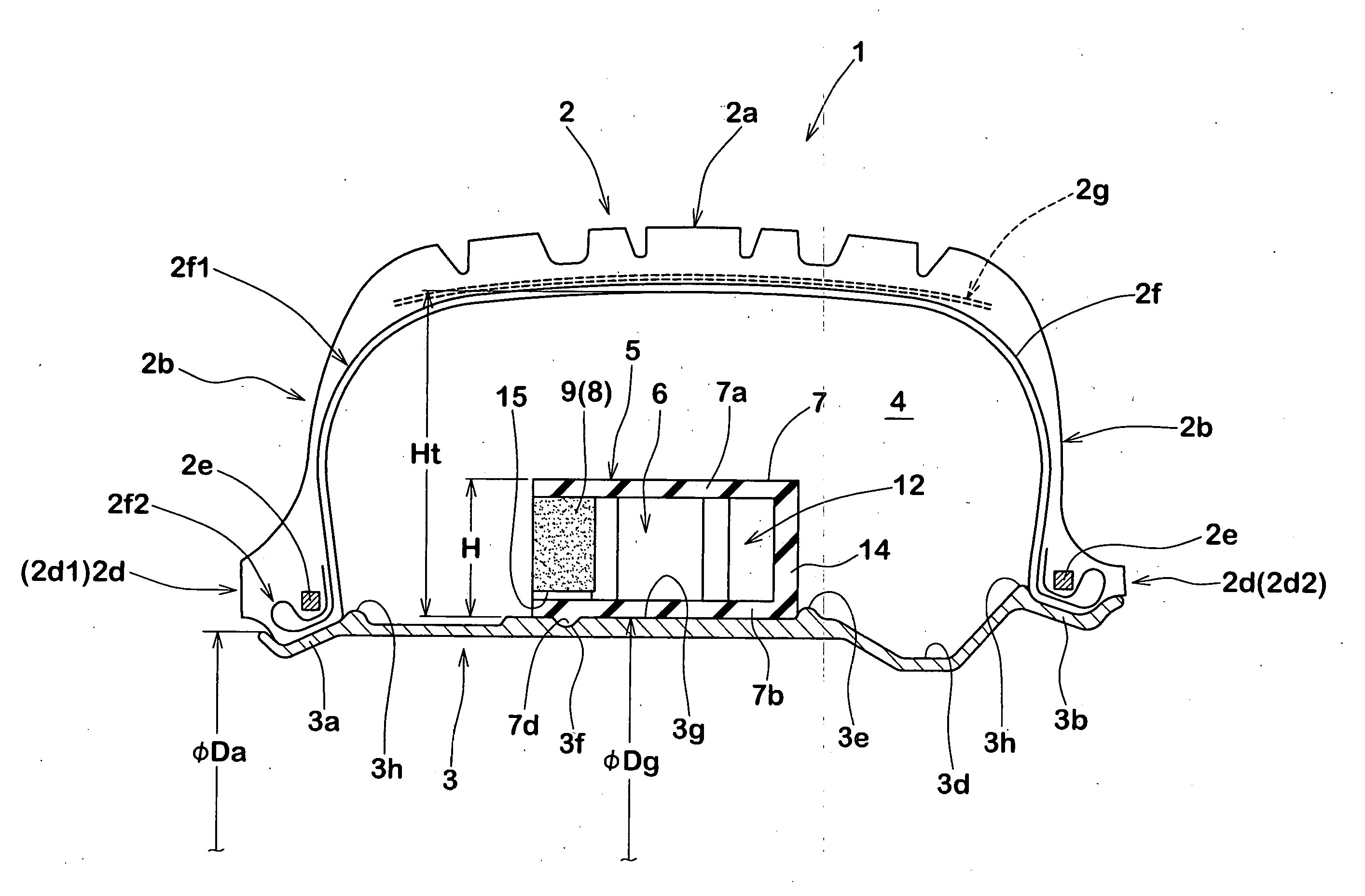
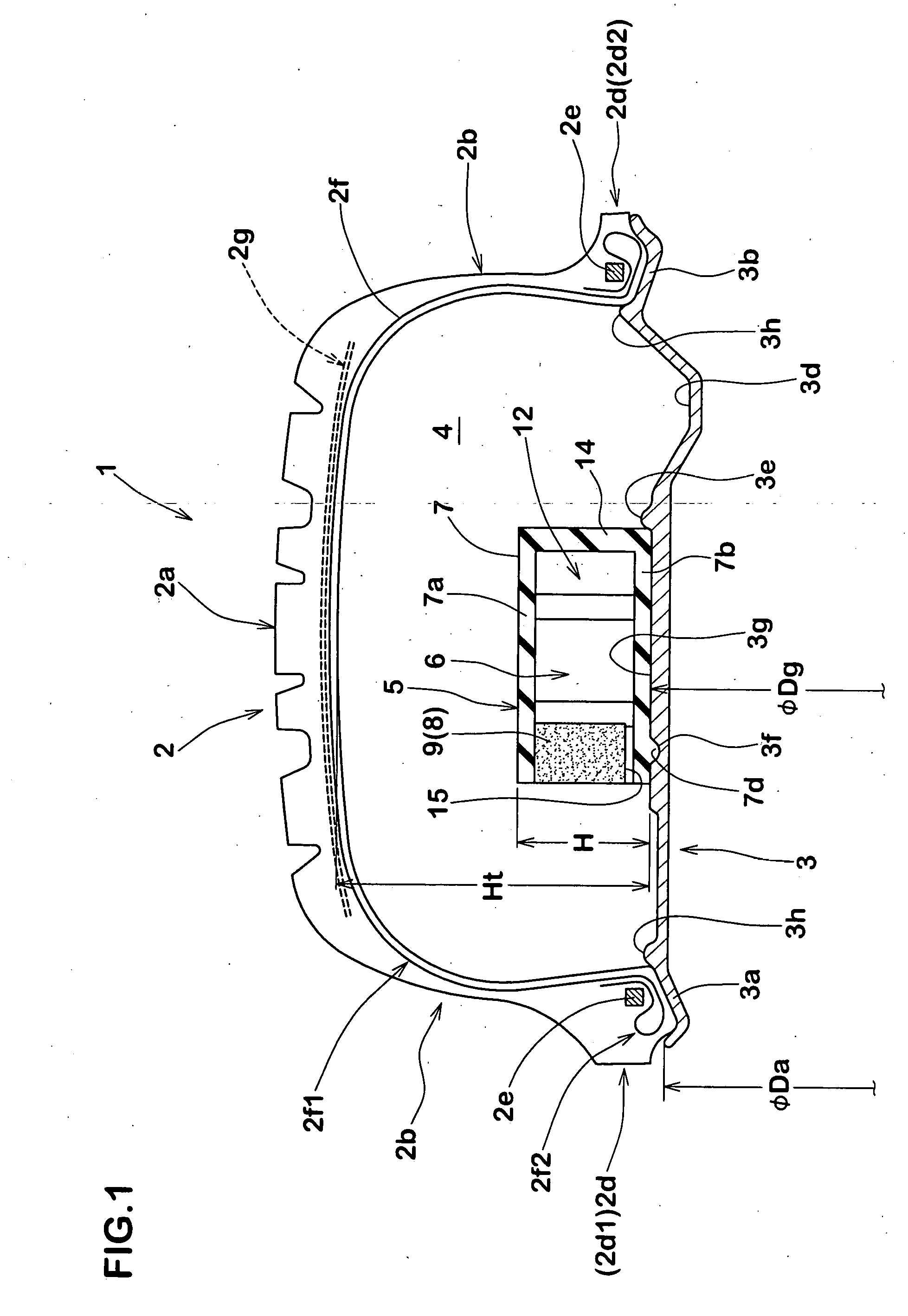
[0071] Runflat systems were prototyped using support rings having a structure shown in FIG. 1. A noise dumper produced based on a specification shown in Table 1 was mounted on each support ring. Tires of 225-680R460A were used, and wheel rims of 225×460A were used. A replica reaction force test was carried out for each system.

[0072] The replica reaction force test was carried out in such a manner that each system was allowed to run on a drum under the following conditions: internal pressure of 200 kPa, load of 5.1 kN, and speed of 60 km / h, variation of axial force in the vertical direction at that time was measured and frequency was analyzed. FIG. 5 shows results of frequency analysis of an example 1 of the present invention and a conventional example. From the frequency analysis, a peak value of axial force variation was obtained, and the value is shown in Table 1 as an evaluation value of running road noise. It has been confirmed that the peak value of the axial force variation c...


PUM


Abstract

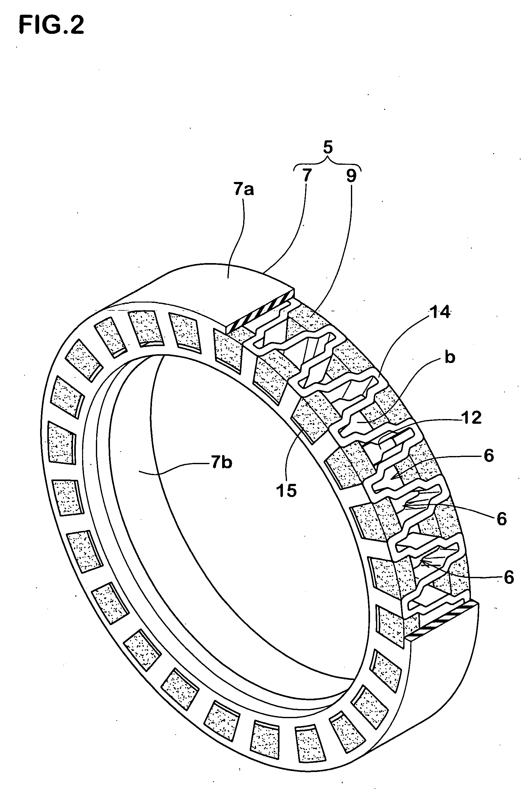
A runflat tire system comprises: a pneumatic tire; a wheel rim on which the pneumatic tire is mounted; and a support ring made of elastic material and disposed in a cavity surrounded by an inner surface of the rim and an inner surface of the tire mounted thereon, wherein the support ring comprises an annular body extending in a circumferential direction of the tire and provided with a plurality of hollows opening at the cavity, and at least one noise dumper made of sponge material having apparent density of 0.1 g / cm3 or less and disposed in the hollow such that the noise dumper does not protrude into the cavity from an inlet surface of the hollow.

Description

BACKGROUND OF THE INVENTION [0001] 1. Field of the Invention [0002] The present invention relates to a runflat tire system which allows a vehicle to run safely at a constant speed through a predetermined distance even when an internal pressure of a tire is lowered. [0003] 2. Description of the Related Art [0004] In recent years, a runflat tire system by which, even if the tire goes flat, it is possible to travel for a very long distance for example several hundred kilometers at a relatively high speed of up to about 80 km / hr has been proposed. [0005]FIG. 8 shows a conventional system of this kind. The system comprises a tire “a”, a wheel rim b on which the tire “a” is mounted, and a support ring e mounted on the wheel rim b in a cavity i surrounded by the tire “a” and the wheel rim b. When an internal pressure of the tire is reduced, the support ring e contacts against an inner surface of a tread portion d to support a load of the tire. The wheel rim b comprises first and second sea...

Claims


Application Information

Patent Timeline
Patent Type & Authority Applications(United States)
IPC IPC(8): B60B21/12B60C5/00B60C17/04B60C17/06B60C19/00
CPCB60C17/06Y10T152/10495B60C17/061B60C19/002
Inventor ISHIDA, TAKAAKITANAKA, MASATOSHITANAMI, YURIE
Owner SUMITOMO RUBBER IND LTD
Learn More