Method and apparatus for efficient vertical fluid delivery for cooling a heat producing device

a heat producing device and fluid delivery technology, applied in the direction of positive displacement liquid engines, lighting and heating apparatus, instruments, etc., can solve the problems of difficult to pump fluid to the heat exchanger b>10/b>, and affecting the cooling effect of the heat producing device, so as to minimize the fluid path distance, prevent heat transfer, and minimize the effect of pressure drop

Inactive Publication Date: 2005-09-29
COOLIGY INC
View PDF99 Cites 85 Cited by
  • Summary
  • Abstract
  • Description
  • Claims
  • Application Information

AI Technical Summary

Problems solved by technology

However, existing microchannels include conventional parallel channel arrangements which are not well suited for cooling heat producing devices which have spatially-varying heat loads.
The large pressure drop formed in the heat exchanger 10 makes pumping fluid to the heat exchanger 10 difficult and augments the instabilities.

Method used


Image

  • Method and apparatus for efficient vertical fluid delivery for cooling a heat producing device
  • Method and apparatus for efficient vertical fluid delivery for cooling a heat producing device
  • Method and apparatus for efficient vertical fluid delivery for cooling a heat producing device

Examples


Embodiment Construction

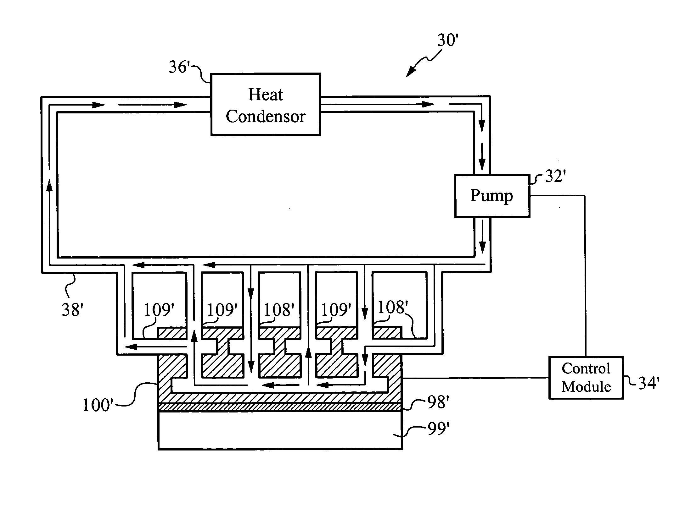
[0047] Generally, the heat exchanger captures thermal energy generated from a heat source by passing fluid through selective areas of the interface layer which is preferably coupled to the heat source. In particular, the fluid is directed to specific areas in the interface layer to cool the hot spots and areas around the hot spots to generally create temperature uniformity across the heat source while maintaining a small pressure drop within the heat exchanger. As discussed in the different embodiments below, the heat exchanger utilizes a plurality of apertures, channels and / or fingers in the manifold layer as well as conduits in the intermediate layer to direct and circulate fluid to and from selected hot spot areas in the interface layer. Alternatively, the heat exchanger includes several ports which are specifically disposed in predetermined locations to directly deliver fluid to and remove fluid from the hot spots to effectively cool the heat source.

[0048] It is apparent to one...


PUM


Abstract

A heat exchanger and method of manufacturing thereof comprises an interface layer for cooling a heat source. The interface layer is coupled to the heat source and is configured to pass fluid therethrough. The heat exchanger further comprises a manifold layer that is coupled to the interface layer. The manifold layer includes at least one first port that is coupled to a first set of individualized holes which channel fluid through the first set. The manifold layer includes at least one second port coupled to a second set of individualized holes which channel fluid through the second set. The first set of holes and second set of holes are arranged to provide a minimized fluid path distance between the first and second ports to adequately cool the heat source. Preferably, each hole in the first set is positioned a closest optimal distance to an adjacent hole the second set.

Description

RELATED APPLICATIONS [0001] This Patent Application is a continuation in part of U.S. patent application Ser. No. 10 / 680,584, filed Oct. 6, 2003, and entitled “METHOD AND APPARATUS FOR EFFICIENT VERTICAL FLUID DELIVERY FOR COOLING A HEAT PRODUCING DEVICE”, hereby incorporated by reference, which is a continuation in part of U.S. patent application, Ser. No. 10 / 439,635, filed May 16, 2003 and entitled, “METHOD AND APPARATUS FOR FLEXIBLE FLUID DELIVERY FOR COOLING DESIRED HOT SPOTS IN A HEAT PRODUCING DEVICE”, hereby incorporated by reference, which claims priority under 35 U.S.C. 119 (e) of the co-pending U.S. Provisional Patent Application, Ser. No. 60 / 423,009, filed Nov. 1, 2002 and entitled, “METHODS FOR FLEXIBLE FLUID DELIVERY AND HOTSPOT COOLING BY MICROCHANNEL HEAT SINKS”, hereby incorporated by reference, as well as co-pending U.S. Provisional Patent Application, Ser. No. 60 / 442,383, filed Jan. 24, 2003 and entitled, “OPTIMIZED PLATE FIN HEAT EXCHANGER FOR CPU COOLING”, which ...

Claims


Application Information

Patent Timeline
Patent Type & Authority Applications(United States)
IPC IPC(8): F04B17/00F04B19/00F28D15/00F28D15/02F28F3/02F28F3/08F28F3/12F28F13/18G06Q20/00H01L23/473H04L29/06
CPCF04B17/00F04B19/006H01L2924/0002F28D15/00F28D15/0266F28D21/0015F28D2021/0029F28F3/02F28F3/086F28F3/12F28F7/02F28F13/06F28F13/185F28F2210/10F28F2260/02G06F1/20G06Q20/20H01L23/473H01L23/4735H01L2924/00
Inventor KENNY, THOMAS W.MUNCH, MARKZHOU, PENGSHOOK, JAMES GILLUPADHYA, GIRISHGOODSON, KENNETHCORBIN, DAVEMCMASTER, MARKLOVETTE, JAMES
Owner COOLIGY INC
Why Eureka
Try Eureka