Multi-level microchannel heat exchangers

Active Publication Date: 2007-01-02
VERTIV CORP
View PDF211 Cites 148 Cited by
  • Summary
  • Abstract
  • Description
  • Claims
  • Application Information

AI Technical Summary

Benefits of technology

[0006]A heat exchanger provides vertically stacked multichannels, which together effectively draw heat away from a heat-generating device. The vertically stacked mu

Problems solved by technology

Overheated components often fail and must be replaced, an expensive and time-consuming process.
For example, these heat sinks do not allow heat-absorbing materials to be concentrated in a specific area.
These heat sinks also suffer from pressure drops along the length of the channels, preventing a uniform flow of a cooling material along the channel.

Method used


Image

  • Multi-level microchannel heat exchangers
  • Multi-level microchannel heat exchangers
  • Multi-level microchannel heat exchangers

Examples


Embodiment Construction

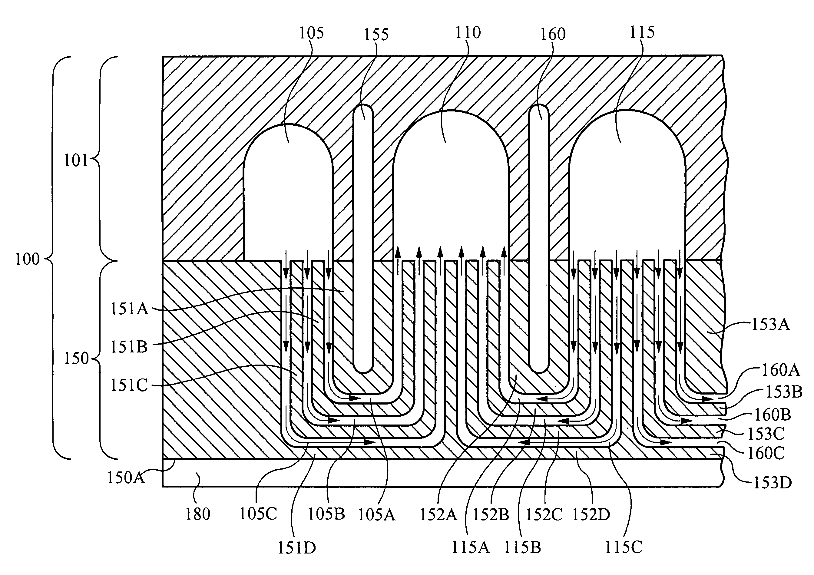
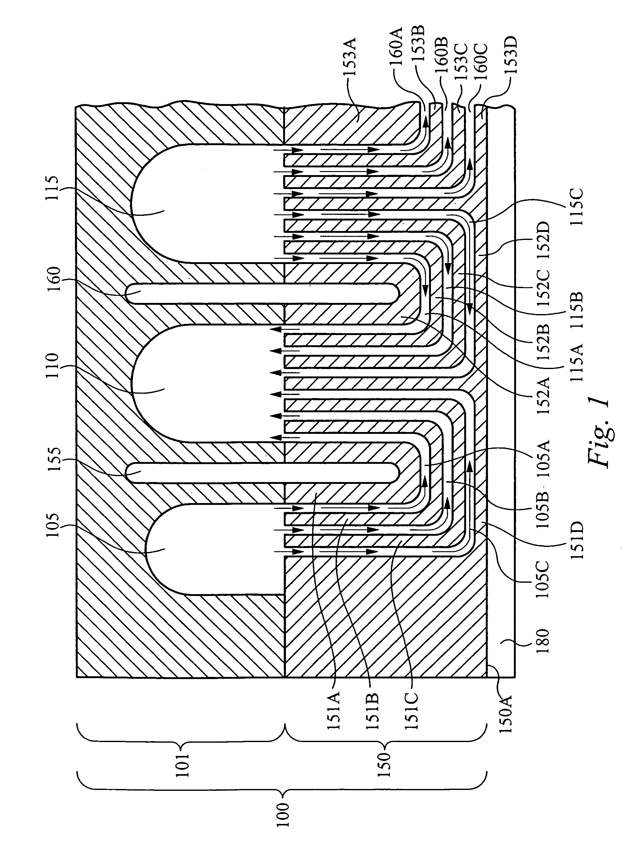
[0028]FIG. 1 is a side cross-sectional view of a section of a heat exchanger 100, in accordance with one embodiment of the present invention, coupled to a heat-generating device 180. The heat exchanger 100 comprises a manifold layer 101 coupled to an interface layer 150. In operation, a cooling (i.e., heat-absorbing) material is introduced into a portion of the manifold layer 101, is transmitted through channels in the interface layer, where it absorbs heat generated by the heat-generating device 180, is transmitted to another portion of the manifold layer 101, and is extracted from the heat exchanger 100. By absorbing and carrying away heat generated by the heat-generating device 180, the cooling material cools the heat-generating device 180. As used herein, the surface at which the heat exchanger couples to a beat-generating device is referred to as a heat-exchanging plane. It will be appreciated that the heat-exchanging plane can be planar or substantially planar, or it can have ...


PUM


Abstract

An apparatus and method of circulating a heat-absorbing material within a heat exchanger. The apparatus comprises a manifold layer coupled to an interface layer. The manifold layer comprises an inlet manifold and an outlet manifold. The interface layer comprises a plurality of channels that extend from the inlet manifold, toward a heat-exchanging plane, and turn away from the heat-exchanging plane, terminating at the outlet manifold. The plurality of channels are stacked in a plane non-parallel to the heat-exchanging plane. Each of the channels is adjacent to another, thus allowing heat radiated from a heat-generating device to be conducted to a cooling material circulating within the channels, away from the heat-generating device. Preferably, each of the channels has a U-shape or an elongated U-shape.

Description

RELATED APPLICATION[0001]This application claims priority under 35 U.S.C. § 119(e) of the co-pending U.S. provisional patent application Ser. No. 60 / 455,729, filed on Mar. 17, 2003, and titled “Microchannel Heat Exchanger Apparatus with Porous Configuration and Method of Manufacturing Thereof.” The provisional patent application Ser. No. 60 / 455,729, filed on Mar. 17, 2003, and titled “Microchannel Heat Exchanger Apparatus with Porous Configuration and Method of Manufacturing Thereof” is hereby incorporated by reference.FIELD OF THE INVENTION[0002]This invention relates to the field of heat exchangers. More specifically, this invention relates to micro-channel structures used in a heat exchanger for carrying heat-absorbing fluids.BACKGROUND OF THE INVENTION[0003]Heat sinks are an important component in many devices, particularly in semiconductor devices, where smaller device-geometries in more powerful circuits generate more heat in a smaller area. Overheated components often fail an...

Claims


Application Information

Patent Timeline
IPC IPC(8): F28D15/00F28F3/00H05K7/20F28DF28F3/12F28F7/00F28F9/02F28F13/00F28F27/02H01L23/34H01L23/473
CPCF28F3/12H01L23/473F28F2260/02H01L2924/0002H01L2924/00F28F2270/00
Inventor LOVETTE, JAMESZHOU, PENGSHOOK, JAMES GILL
Owner VERTIV CORP
Why Eureka
Try Eureka