Apparatus and method for optimizing the use of oxygen in the direct reduction of iron

a technology of oxygen and direct reduction, applied in lighting and heating apparatus, manufacturing converters, furnaces, etc., can solve the problems of reducing the kinetics of the desired iron reduction reaction, not wanting carbon dioxide, and not wanting free oxygen in the reducing gas, so as to increase the amount of reducing gas, and improve the effect of reducing quality

Inactive Publication Date: 2002-01-24
MIDREX TECH INC
View PDF0 Cites 24 Cited by
  • Summary
  • Abstract
  • Description
  • Claims
  • Application Information

AI Technical Summary

Benefits of technology

0013] Another object of the invention is to provide means for increasing the amount of reducing gas generated, particularly H.sub.2 and CO, from the combustion of oxygen and fuel, and to produce a high quality reducing gas by combustion of oxygen and fuel, particularly natural gas.
0014] Another object of the invention is to provide means for increasing the amount of reducing gas generated, particularly H.sub.2 and CO, from the combustion of oxygen and fuel, and to produce a high quality reducing gas by combustion of oxygen and fuel, particularly natural gas, while accurately controlling the temperature of the reducing gas stream.
0015] Another object of the invention is to generate reducing gas, particularly H.sub.2 and CO, from the combustion of oxygen and fuel, particularly natural gas, while accurately controlling the concentration of methane / hydrocarbons in the reducing gas stream.
0016] Another object of the invention is to provide means for increasing the amount of reducing gas generated, particularly H.sub.2 and CO, from the combustion of oxygen and fuel, and to produce a high quality reducing gas by combustion of oxygen and fuel, particularly natural gas, while accurately controlling the temperature of the reducing gas stream and simultaneously controlling the level of methane / hydrocarbons in the gas stream.
0017] Another object of the invention is to provide means for generating reducing gas, particularly H.sub.2 and CO, from the combustion of oxygen and fuel, particularly natural gas, while simultaneously minimizing the temperature of the reducing gas stream, for a given oxygen to fuel ratio, and minimizing the cost of the apparatus that generates the reducing gas.
0018] The present invention is an apparatus and method for increasing the amount of reducing gas within the reducing gas stream of a direct reduction furnace, while also simultaneously controlling the temperature of the reducing gas stream, and the temperature of the reduction reactor. The method improves the efficiency of direct reduction, by removing and reforming spent reducing gas from a direct reduction furnace to form a high percentage of H.sub.2 and CO therein for use as bustle gas, injecting hydrocarbon-containing enrichment gas into the bustle gas, injecting an oxygen-hydrocarbon gas mixture into the bustle gas and combusting the mixture, and introducing the hydrocarbon-enriched bustle gas into the direct reduction furnace. The apparatus is a refractory lined shaft through which reducing gas, also called bustle gas, passes before entering the direct reduction furnace. The improved apparatus has two main sections, an enrichment section and an oxygen / fuel injection section which communicate with the bustle of the shaft.

Problems solved by technology

Carbon dioxide is not desired because of its inability to reduce iron oxides.
Excessive amounts of hydrocarbons are not desired because they react endothermically upon entering the reactor, which reduces the kinetics of the desired iron reduction reactions.
And, of course, free oxygen is not desired in the reducing gas because of its tendency to re-oxidize reduced iron.
Excessive reducing gas temperatures will cause sintering of the metal and plugging of the reducing reactor.
However, the use of oxy-fuel burners does not allow independent control of reducing gas temperature and reduction reactor temperature, because oxy-fuel burners must be operated within certain limits of oxygen and fuel throughput to obtain good conversion of fuel to reductant, to prevent soot formation, to prevent overheating of the burner, and to maintain flame stability.
Also, the use of oxy-fuel burners is often prohibitively expensive.
At this stage, excess O.sub.2 is undesirable for two reasons.
Second, limited O.sub.2 combusted with the hydrocarbons provided by oxy-fuel injection system 26 results in incomplete combustion of the hydrocarbon stream, producing CO and H.sub.2 as products rather than the CO.sub.2 and H.sub.2O which would theoretically result from complete combustion.

Method used


Image

  • Apparatus and method for optimizing the use of oxygen in the direct reduction of iron
  • Apparatus and method for optimizing the use of oxygen in the direct reduction of iron
  • Apparatus and method for optimizing the use of oxygen in the direct reduction of iron

Examples


case 1 case 2

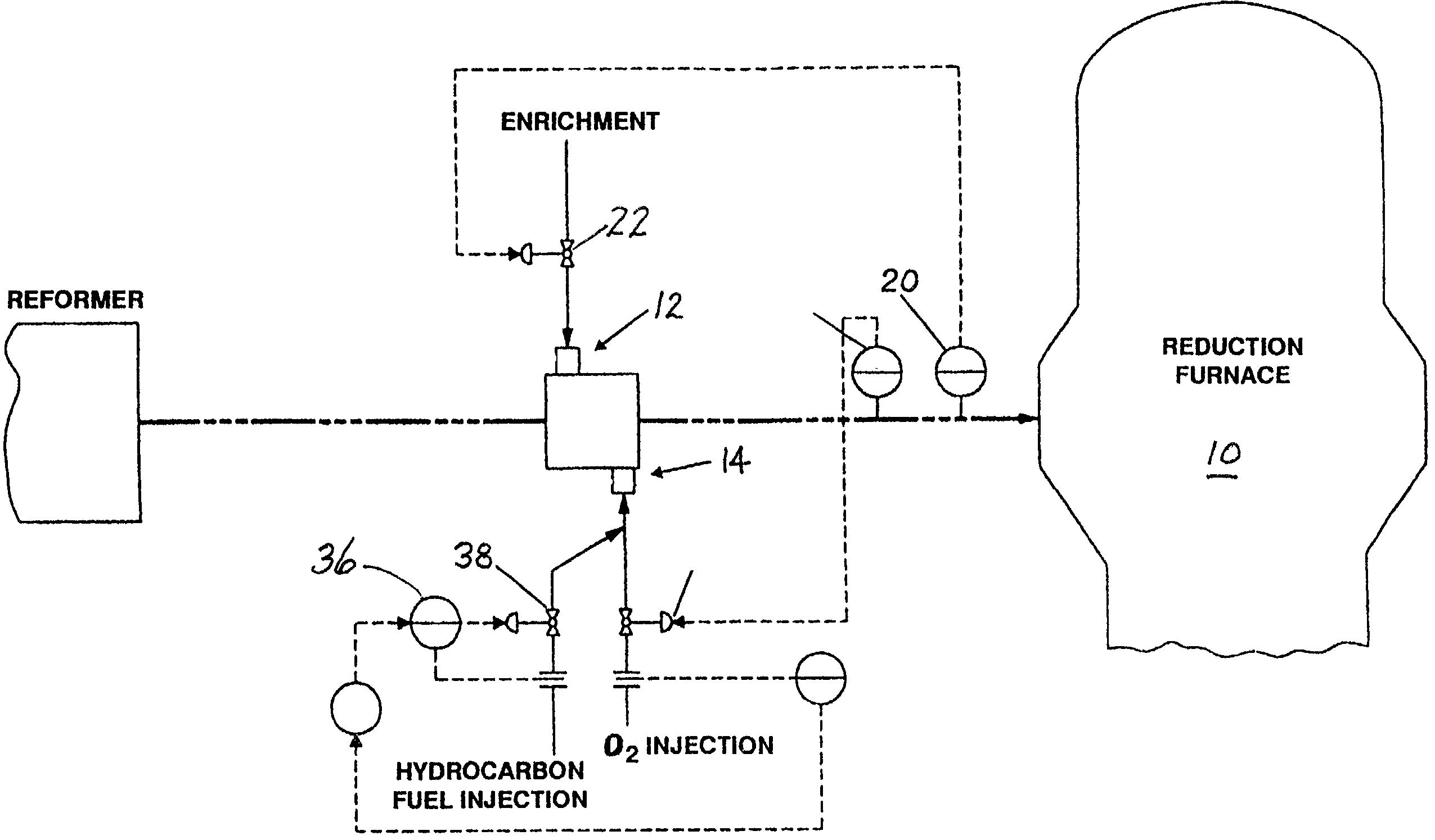
1 Case 1 Case 2 Measured Bustle Gas Temp 1050.degree. C. 1050.degree. C. Measured Reduction Shaft Temp 850.degree. C. 900.degree. C. Measured Bustle Gas CH.sub.4 4.72% wet 3.30% wet Oxygen / Fuel Injection Flow (O.sub.2) 3766 Nm.sup.3 / h 3141 Nm.sup.3 / h Oxygen / Fuel Injection Flow (Hydrocarbon) 6277 Nm.sup.3 / h 5235 Nm.sup.3 / h Enrichment Flow (Hydrocarbon) 5923 Nm.sup.3 / h 1490 Nm.sup.3 / h

SUMMARY OF THE ACHIEVEMENT OF THE OBJECTS OF THE INVENTION

[0050] From the foregoing, it is readily apparent that we have invented an improved method and apparatus for optimizing the use of oxygen in the direct reduction of iron which may be utilized to increase the amount of reductant generated from the combustion of oxygen and fuel relative to the current oxygen injection systems; which is capable of producing a higher quality reducing gas than present oxygen injection systems; and which can accurately control the temperature of the gas stream and control the level of methane / hydrocarbons in the reducing...


PUM

PropertyMeasurementUnit
temperatureaaaaaaaaaa
angleaaaaaaaaaa
angleaaaaaaaaaa

Abstract

An apparatus and method for adjusting the parameters of a reducing gas stream prior to introduction into a direct reduction furnace, such parameters including temperature of the gas stream, and amount of hydrocarbon, carbon monoxide, and hydrogen contained in the reducing gas. The apparatus is placed in-line with the reducing gas recycle loop of a direct reduction furnace, which has an enrichment section which introduces hydrocarbon components to the main stream, and an oxygen/fuel injection system, located downstream from the enrichment section, which injects a shrouded stream of oxygen and hydrocarbon gas into the reducing gas stream. Temperature, carbon monoxide content, and hydrogen content of the reducing gas are adjusted by controlling the flow of oxygen and the ratio of hydrocarbon to oxygen injected in the oxygen/fuel injection system. Hydrocarbon content of the reducing gas is adjusted primarily by controlling the flow rate of the enrichment section.

Description

[0001] This application claims the benefit of U.S. Provisional application Ser. No. 60 / 191,680, filed on Mar. 23, 2000, and is a continuation in part of co-pending U.S. patent application Ser. No. 09 / 781,816, filed Feb. 12, 2001, which is a continuation in part of co-pending U.S. patent application Ser. No. 09,456,111, filed Dec. 7, 1999, which is a continuation in part of U.S. patent application Ser. No. 08 / 924,686, filed Sep. 5, 1997, now U.S. Pat. No. 5,997,5 96, which issued Dec. 7, 1999.[0002] The present invention relates an apparatus and method for the direct reduction of iron oxide, and more particularly to an apparatus and method for the reformation or modification of reducing gas for use with a direct reduction furnace.[0003] The production of direct reduced iron in a vertical shaft reactor involves reduction of the ore in a reduction zone through which is passed a suitable hot reducing gas, known as bustle gas, largely composed of carbon monoxide and hydrogen at temperatu...

Claims


Application Information

Patent Timeline
Patent Type & Authority Applications(United States)
IPC IPC(8): B01J19/26C01B3/36C01B3/38C21B5/00C21B13/00C21B13/02C21C5/52C21C5/56C22B5/12F23C6/04
CPCB01J19/26B01J2219/00058B01J2219/00094B01J2219/00123B01J2219/00155B01J2219/00157B01J2219/00159B01J2219/00164C01B3/363C01B3/384C01B2203/0233C01B2203/0255C01B2203/0816C01B2203/0822C01B2203/141C01B2203/142C21B13/0073C21B13/02C22B5/12F23C6/047C21B2100/64Y02P10/134Y02P20/10
Inventor MONTAGUE, STEPHEN C.VOELKER, BRIAN W.KAKALEY, RUSSELL
Owner MIDREX TECH INC
Why Eureka
Try Eureka