Fuel cell power plant having a fuel concentration sensor cell

a fuel cell and sensor cell technology, applied in the direction of fuel cells, fuel cells, cell components, etc., can solve the problems of increasing the cost and volume of the fuel cell power plant, irreversible damage to the insufficient amount of hydrogen fuel within the fuel cell of the plant, so as to achieve accurate measurement of the hydrogen concentration difference and increase the recycling of fuel

Active Publication Date: 2005-12-20
AUDI AG
View PDF6 Cites 18 Cited by
  • Summary
  • Abstract
  • Description
  • Claims
  • Application Information

AI Technical Summary

Benefits of technology

[0006]The plant also includes a porous sensor water transport plate secured in fluid communication with the sensor cell, for directing a cooling fluid which is a water stream to pass adjacent the sensor cell to remove heat and condensate water from the sensor cell and to maintain humidification of the membrane electrode assembly. A controller means is also included for controlling operation of the fuel cell, and the controller is secured in electrical communication with the detector and a fuel inlet valve so that the controller means may vary a rate of fuel passing through the fuel cell in response to the detected voltage. In various embodiments, the controller may communicate with and control fuel and / or oxygen inlet valves providing fuel and oxygen to a hydrocarbon fuel processor, such as a steam reformer, auto thermal reformer, or catalyzed partial oxidation reformer, which in turn provide the fuel to the fuel cell. Alternatively, the fuel inlet valve may be for a pure hydrogen fuel source fed directly to the fuel cell. The fuel inlet valve may also be a fuel valve means for increasing fuel to the fuel cell, including a fuel recycle blower secured on a fuel recycle line in fluid communication between the fuel exhaust and fuel inlet for increasing recycling of fuel from the fuel exhaust to the fuel inlet.
[0007]In a preferred embodiment, a portion of the fuel exhaust stream is directed to flow through the anode flow field of the sensor cell and no fluid is directed through the cathode flow field of the sensor cell while at the same time the power circuit is closed so that current is directed to the membrane electrode assembly of the sensor cell. That effectively turns the sensor cell into a hydrogen pump so that hydrogen is evolved at the cathode flow field providing a very accurate measurement of a hydrogen concentration difference between the anode and cathode flow fields of the sensor cell. The sensor cell may be calibrated prior to usage, so that at a variety of known currents and known hydrogen concentration differentials between the anode and cathode flow fields, specific voltages are identified. By calibrating the sensor cell in such a manner, changes in the voltage detected by the detector will accurately measure changes in the hydrogen concentration of the fuel cell exhaust stream so that the controller may rapidly and precisely adjust the rate of fuel supply to the fuel cell to satisfy demand for current while avoiding an inadequate supply of fuel within the fuel cell or fuel cells of the power plant.
[0008]In an alternative embodiment, a portion of the fuel exhaust stream may be directed to flow adjacent one side of the sensor cell membrane electrode assembly, such as through the cathode flow field, while a portion of a fuel inlet stream is directed to flow adjacent the opposed side of the membrane electrode assembly, such as through the anode flow field. Such an embodiment provides additional safeguards against local cathode side flow blockages should material wettability deficiencies cause channel blockage by water, and this embodiment does not require a power supply directing electrical current to the sensor cell.
[0011]Additionally, the sensor cell may be secured to be integral with a fuel cell stack assembly sharing a common coolant inlet and outlet manifold, or may be secured separately from the fuel cell or fuel cell stack assembly. Also, the sensor water transport plate may be secured adjacent to either the anode or cathode or both flow fields of the sensor cell. In an additional embodiment, to minimize any possibility of carbon corrosion of catalysts of the membrane electrode assembly of the sensor cell, the catalysts may be secured without any carbon, for example as platinum black. In a further embodiment, an electrode of the sensor cell may contain a palladium black catalyst in order to provide a more stable reference potential due to formation of a palladium hydride.
[0013]It is a more specific purpose to provide a fuel cell power plant having a fuel concentration sensor cell that can reliably, precisely and quickly detect a hydrogen fuel concentration within a fuel cell or fuel cells of the plant so that fuel supply to the fuel cell may be adjusted in response to the detected changed in fuel concentration.

Problems solved by technology

In fuel cell power plants of the prior art, it is known that a sudden increase in an electrical load on the plant may result in an inadequate amount of hydrogen fuel within fuel cells of the plant.
Failure to supply adequate hydrogen to the fuel cells of the plant results in many problems, including corrosion of common carbon support materials that support electrode catalysts.
Such corrosion quickly leads to irreversible damage to fuel cells of the plant.
Burners, however, increase a cost and volume of a fuel cell power plant.
A result of the differential in temperatures and dew points of the fuel streams can result in condensation of water within the cell that can lead to blockage of flow channels or flooding of diffusion layers adjacent the membrane electrode assembly, all of which will negatively impact the voltage detected across the membrane electrode assembly.
Additionally, a PEM electrolyte of a membrane electrolyte assembly must not be allowed to dry out if it is to provide reproducible performance of the sensor cell.

Method used


Image

  • Fuel cell power plant having a fuel concentration sensor cell
  • Fuel cell power plant having a fuel concentration sensor cell
  • Fuel cell power plant having a fuel concentration sensor cell

Examples


Embodiment Construction

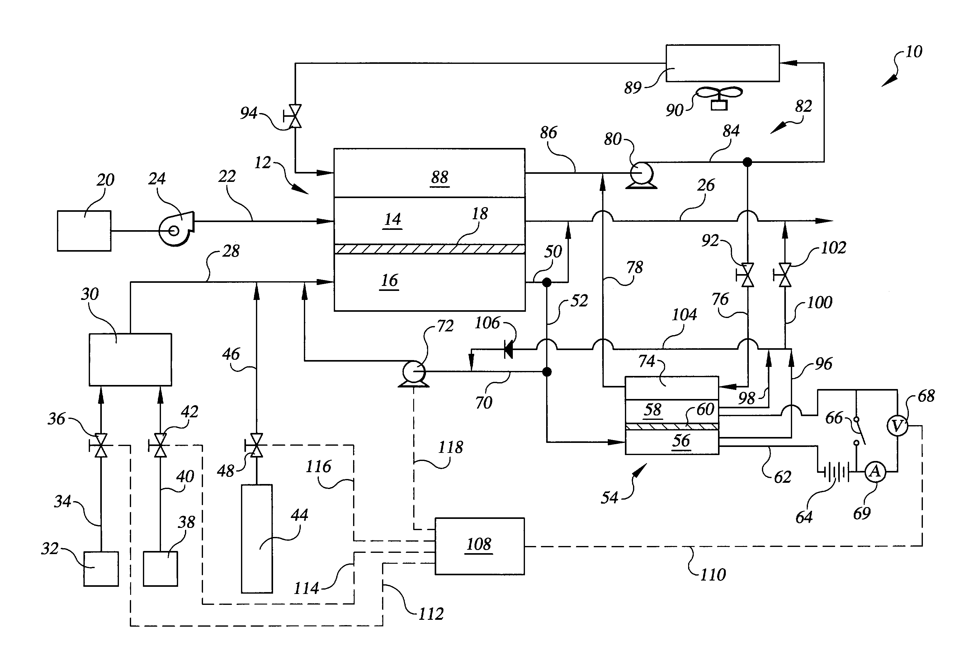
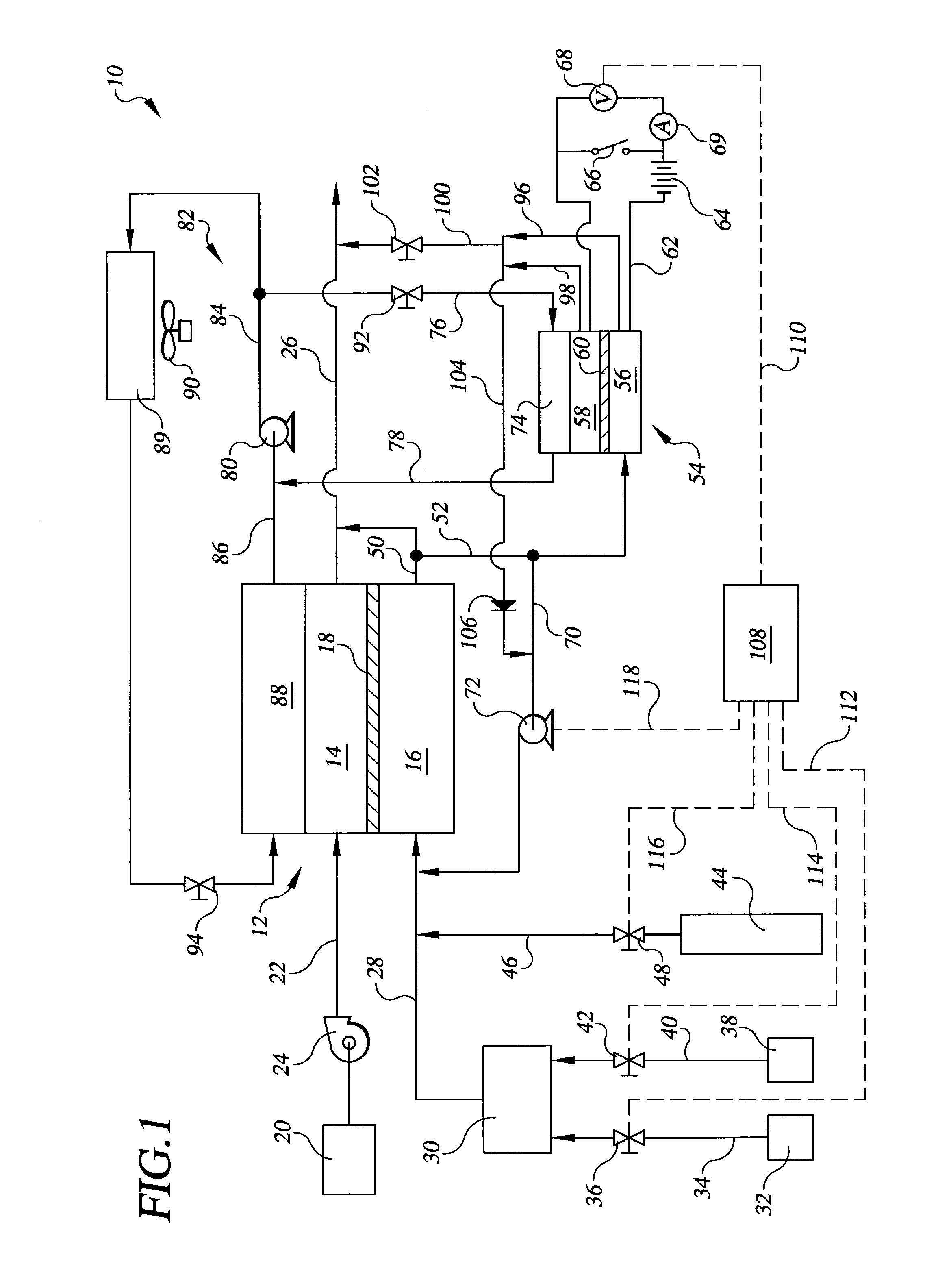
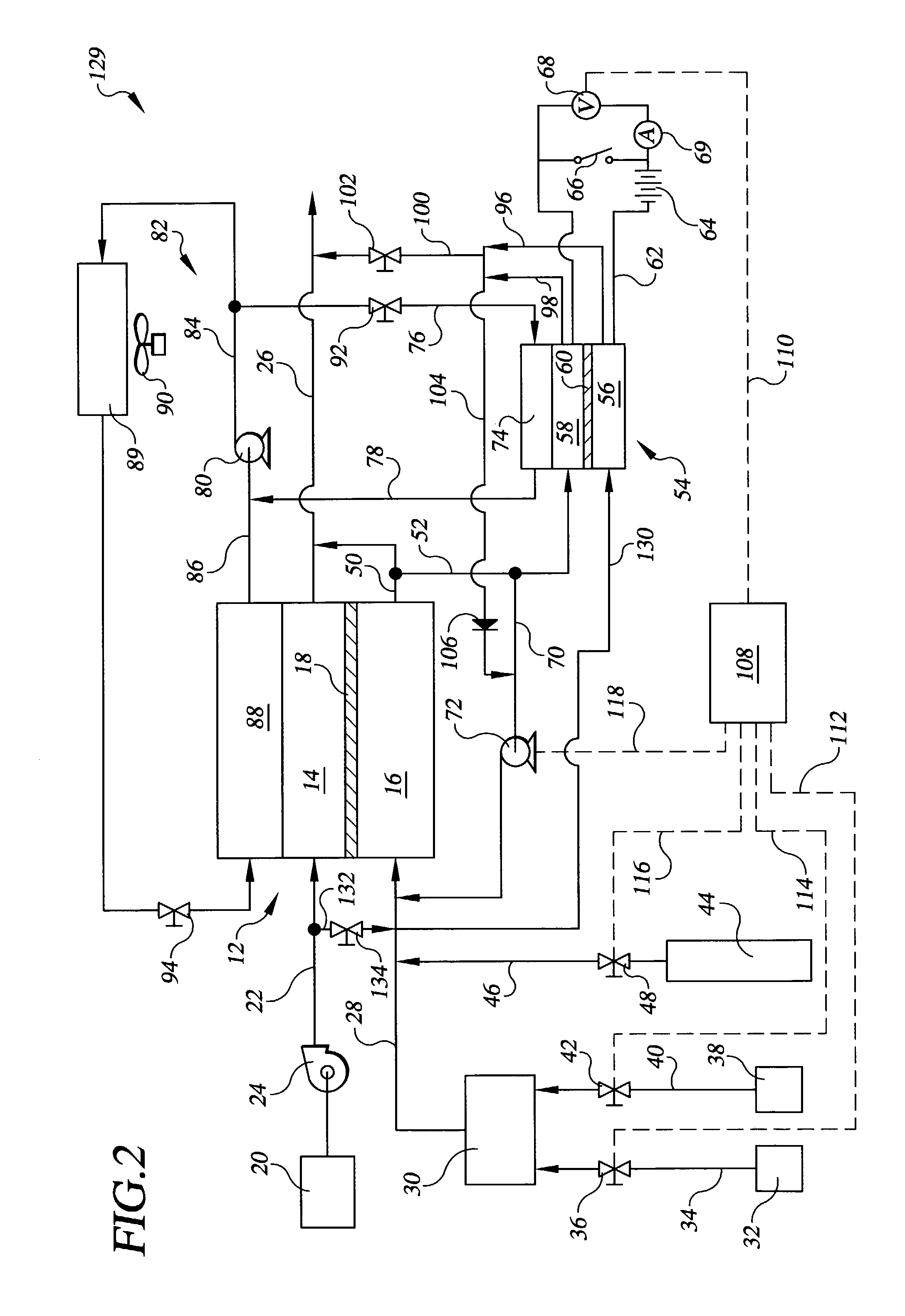
[0018]Referring to the drawings in detail, a fuel cell power plant having a fuel concentration sensor cell constructed in accordance with the present invention is shown in FIG. 1, and is generally designated by the reference numeral 10. The power plant 10 includes at least one fuel cell 12 having a cathode flow field 14 and an anode flow field 16 disposed on opposed sides of a membrane electrode assembly 18 in a manner well known in the art. An oxidant source 20 supplies an oxidant such as air through an oxidant inlet 22 to the cathode flow field 14. The oxidant inlet 22 may have a blower 24 to increase the pressure of the oxidant. The oxidant passes out of the cathode flow field 14 and fuel cell 12 through an oxidant exhaust 26 to be vented out of the fuel cell 12. A hydrogen rich reducing fluid fuel is supplied to the anode flow field 16 as a fuel inlet stream passing through a fuel inlet 28. The fuel may be produced by a fuel processor of fuel processing system 30 well known in t...


PUM

PropertyMeasurementUnit
electrical currentaaaaaaaaaa
concentrationaaaaaaaaaa
electrical communicationaaaaaaaaaa

Abstract

A fuel cell power plant (10) having a fuel concentration sensor cell (54) is disclosed for detecting a concentration of fuel in a fuel cell (12) of the plant (10). A portion of a fuel exhaust stream is directed to flow through the sensor cell (54) adjacent to a membrane electrode assembly (60) of the sensor cell (54). A power circuit (62) may or may not deliver an electrical current to the cell (12), while changes in voltage across the cell (12) that are proportional to changes in hydrogen concentrations within the fuel exhaust stream are detected by a detector (68) which communicates the changes to a controller (108) for controlling a rate of fuel supply to the fuel cell (12). A porous sensor water transport plate (74) cools, humidifies delivers and removes liquid from the sensor cell (12).

Description

TECHNICAL FIELD[0001]The present invention relates to fuel cell power plants that are suited for usage in transportation vehicles, portable power plants, or as stationary power plants, and the invention especially relates to a fuel cell power plant having a sensor cell that detects a concentration of a hydrogen containing reducing fluid fuel in fuel cells of the plant.BACKGROUND ART[0002]Fuel cells are well known and are commonly used to produce electrical energy from hydrogen containing reducing fluid and oxygen containing oxidant reactant streams to power electrical apparatus such as motors, and transportation vehicles, etc. A fuel cell power plant may include a plurality of fuel cells arranged in a well known cell stack assembly along with various support systems, such as hydrocarbon fuel processors, thermal management systems, etc. In fuel cell power plants of the prior art, it is known that a sudden increase in an electrical load on the plant may result in an inadequate amount ...

Claims


Application Information

Patent Timeline
Patent Type & Authority Patents(United States)
IPC IPC(8): H01M4/92H01M8/00H01M8/04H01M8/10
CPCH01M4/92H01M8/04089H01M8/04462H01M8/04753H01M8/1004H01M8/04567H01M8/04597H01M8/04783Y02E60/521Y02E60/50
Inventor BALLIET, RYAN J.JARVI, THOMAS D.PEDERSEN, LARS M.PERRY, MICHAEL L.REISER, CARL A.
Owner AUDI AG
Why Eureka
Try Eureka