
Eureka
For R&D, Eureka makes reading and utilizing patents & technical documents easy.
Eureka AIR
Designed for self-driven R&D workflows. Generate viable solutions, solve complex R&D challenges, empower your innovation with AI.

Eureka Materials
Designed for material experts only. Revolutionize your material R&D, from search, analyze, to developing new materials.

TechResearch
Generate reliable direction feasibility study reports for your R&D in just a few steps.

TechSeek
Discover and master advanced knowledge NOW. Basics, ideas, possibilities, all at once.

TechMind
As an expert in R&D Theories, TechMind can generates customized viable solutions instantly.

TechRisk
Analyze your overall solution with one click, know your potential R&D risks in advance.

TechMonitor
Get weekly tech updates, stay abreast of the latest tech innovations and key insights.
Light emitting diode
- Summary
- Abstract
- Description
- Claims
- Application Information
AI Technical Summary
Benefits of technology
Problems solved by technology
Method used
Image

Examples
first embodiment
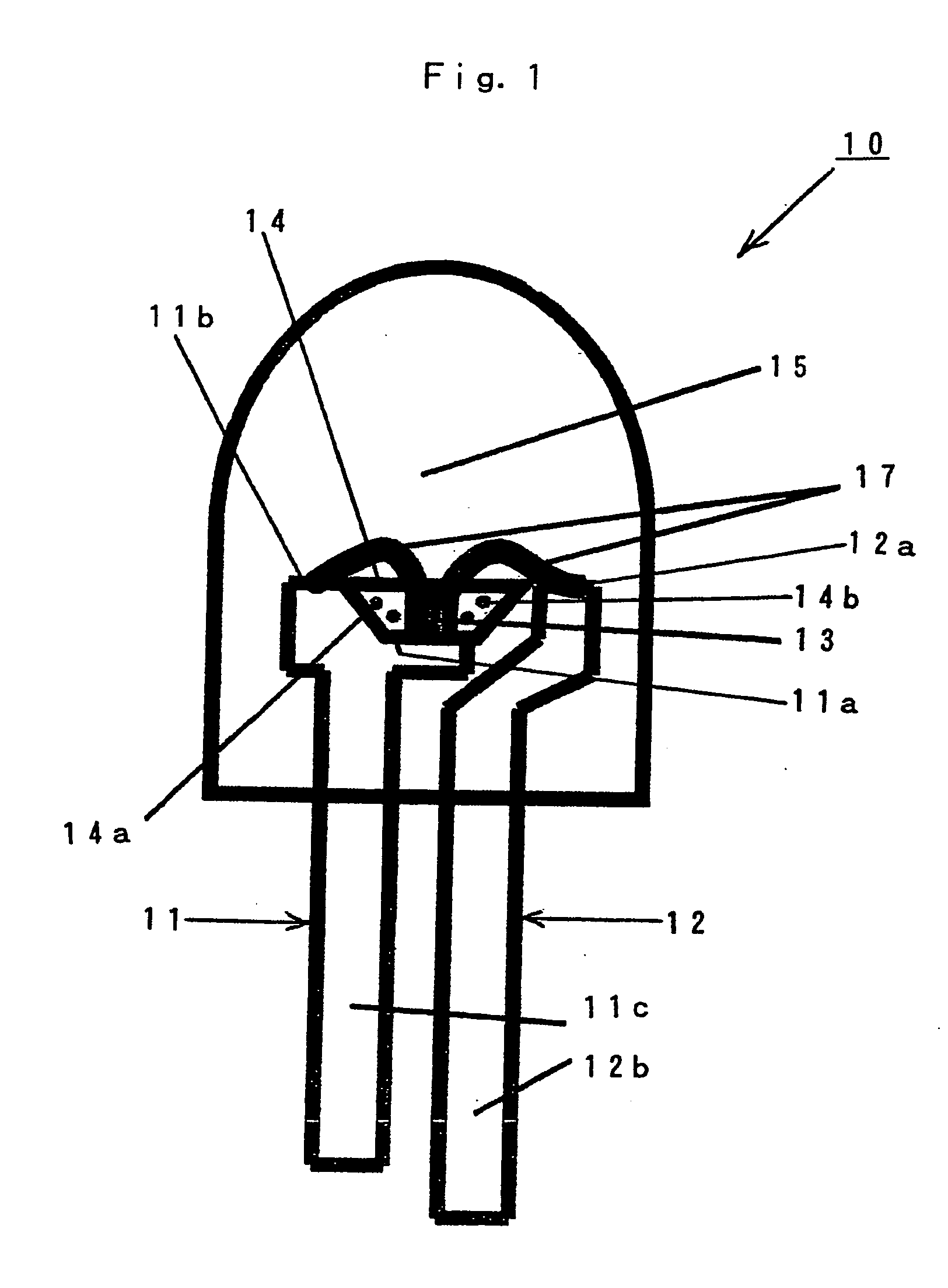
[0046]FIG. 1 shows a configuration of an LED made in accordance with the principles of the invention. In FIG. 1, an LED 10 can be configured as a so-called shell-shaped LED and can include a pair of lead frames 11 and 12, a blue LED chip 13 mounted on top of a chip mounting portion 11a formed on the upper end surface of the lead frame 11, and a clear resin portion 14 formed soas to be adjacent to and / or surround the blue LED chip 13 on top of the chip mounting portion 11a of the lead frame 11. A phosphor 14a can be mixed into the clear resin portion 14 and a lens portion 15 can be formed with a mold resin so as to be adjacent to and / or surround the upper ends of the lead frames 11 and 12, the blue LED chip 13 and the clear resin portion 14.
[0047] The lead frames 11 and 12 can be formed out of a conductive material such as aluminum and can be provided with the chip mounting portion 11a and bonding portions 11b and 12a at the respective upper ends thereof. Whereas the other ends of th...
second embodiment
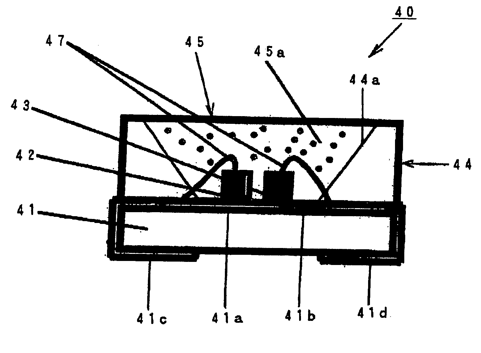
[0056]FIG. 3 shows a configuration of an LED. In FIG. 3, an LED 20 is configured as a so-called surface-mount LED and can include a chip substrate 21, a blue LED chip 22 mounted on top of the chip substrate 21, a frame-shaped member 23 formed on top of the chip substrate 21 such that it is adjacent to and / or surrounds the blue LED chip 22. A clear resin portion 24 can be charged into a recessed portion 23a of the frame-shaped member 23 to cover the blue LED chip 22.
[0057] It is to be noted that the blue LED chip 22 and the clear resin portion 24 can have the same configuration as in the LED chip 13, and that the clear resin portion 14 of the LED 10 shown in FIG. 1 can be omitted.
[0058] The chip substrate 21 can be made of a heat-resistant resin and include a flat copper clad wired board. A chip mounting land 21a, and an electrode land 21b can be provided on a surface of the chip substrate 21. Surface-mount terminal portions 21c and 21d can be configured such that they extend around...
third embodiment
[0065]FIG. 4 shows a configuration of an LED made in accordance with the principles of the invention. In FIG. 4, an LED 30 can be configured as a so-called shell-shaped LED and can include a pair of lead frames 31 and 32, a blue LED chip 33, and a red LED chip 34 mounted adjacent each other on top of a chip mounting portion 31a formed on the upper end surface of the lead frame 31, and a clear resin portion 35 formed so as to be adjacent to and / or surround the blue LED chip 33 and the red LED chip 34 on top of the chip mounting portion 31a of the lead frame 31. A phosphor 35a can be mixed into the clear resin portion 35 and a lens portion 36 can be formed with a mold resin so as to be adjacent to and / or surround the upper ends of the lead frames 31 and 32, the blue LED chip 33, the red LED chip 34 and the clear resin portion 35.
[0066] The lead frames 31 and 32 can be formed out of a conductive material such as aluminum and can be provided with the chip mounting portion 31a and bondin...
PUM
 Abstract
Description
Claims
Application Information
 - R&D Engineer
- R&D Manager
- IP Professional
- Industry Leading Data Capabilities
- Powerful AI technology
- Patent DNA Extraction
Browse by: Latest US Patents, China's latest patents, Technical Efficacy Thesaurus, Application Domain, Technology Topic, Popular Technical Reports.
© 2024 PatSnap. All rights reserved.Legal|Privacy policy|Modern Slavery Act Transparency Statement|Sitemap|About US| Contact US: help@patsnap.com