
Lamp with integral power supply

Inactive Publication Date: 2005-09-29
LEDVANCE LLC
View PDF4 Cites 11 Cited by
  • Summary
  • Abstract
  • Description
  • Claims
  • Application Information

AI Technical Summary

Benefits of technology

[0004] It is another object of the invention to enhance the operation of lamps generally.
[0005] It is yet another object of the invention to enhance the operation of lamps employing heat-sensitive circuitry.
[0006] Yet another object of the invention is to enhance the operation and life of halogen lamps employing voltage-reducing circuitry.
[0009] This procedure increases the life of the component and thus the life of the lamp.

Problems solved by technology

These components are subjected to various temperature levels during operation of the lamp and, since most of the components are limited to a maximum operating temperature of 120° C., this limiting factor has compromised the lamp operation.

Method used


Image

  • Lamp with integral power supply
  • Lamp with integral power supply
  • Lamp with integral power supply

Examples


Embodiment Construction

[0014] For a better understanding of the present invention, together with other and further objects, advantages and capabilities thereof, reference is made to the following disclosure and appended claims taken in conjunction with the above-described drawings.

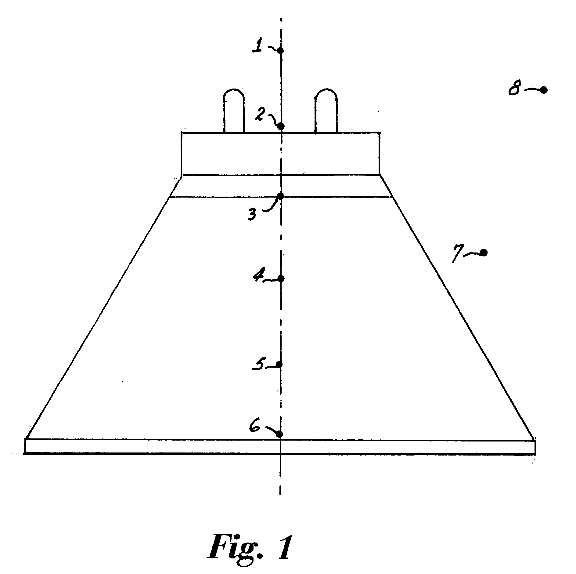
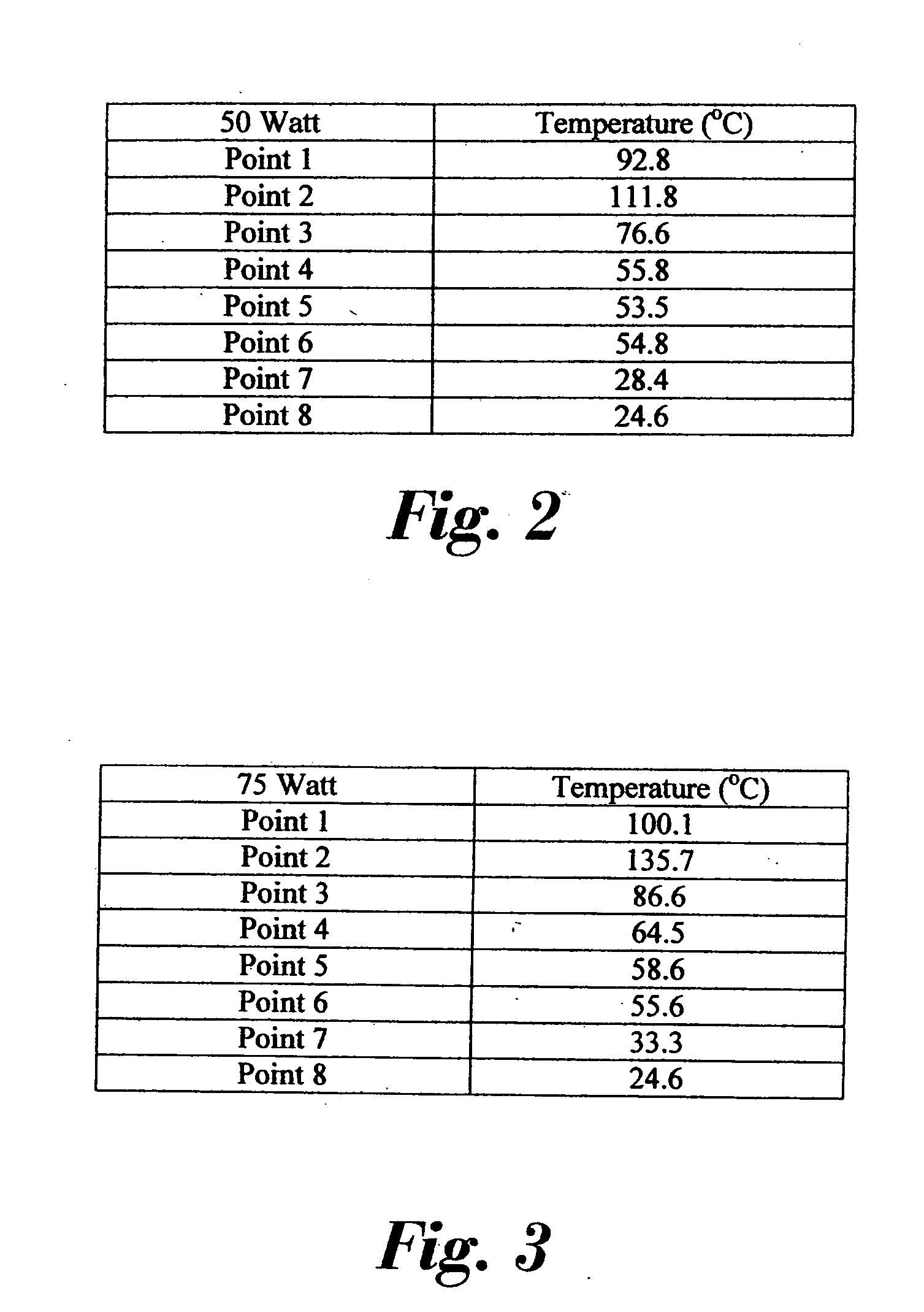
[0015] Referring now to the drawings with greater particularity, there is shown in FIG. 1 a diagrammatic representation of a PAR 38 lamp envelope with the base removed and with various temperature points illustrated by the numbers 1-8. Points 2-6 are at the glass surface, Point 1 is approximately 32 mm above the reflector, Point 7 is approximately 12 mm from the reflector and Point 8 represents the ambient temperature. The temperature measurements for Points 1 and 2 were made with the lamp base in place. The actual temperatures for a 50 Watt lamp and a 75 Watt lamp are shown respectively in FIGS. 2 and 3.

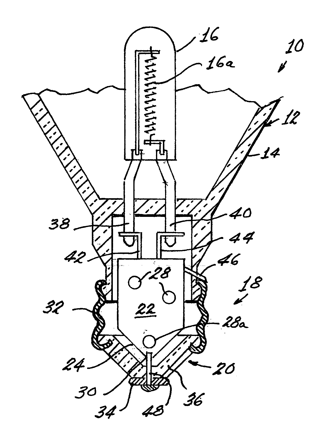
[0016] Referring now to FIG. 4, there is shown a lamp 10 including an envelope 12 having a body 14 with a light source capsu...


PUM


Abstract

A lamp (10) includes an envelope (12) having a body (14) with a light source capsule (16) contained therein and ending in a hollow base (18) that terminates in a conical end (20). A circuit board (22) is positioned within the hollow base (18) and includes a triangular portion (24) that is closely fitted within the conical end (20). A temperature sensitive, voltage reducing component (28a) is positioned near the apex (30) of the triangular portion (24).

Description

TECHNICAL FIELD [0001] This invention relates to electric lamps and more particularly to electric lamps employing internal circuitry such as an integral voltage-reducing device. BACKGROUND ART [0002] Various methods exist for reducing the voltage to electric lamps for purposes of extending the life times of the lamps. It also has been proposed that the voltage reducing circuitry necessary to accomplish this function be incorporated directly into the lamp, for example, in the lamp base. The procedure is often used with encapsulated halogen lamps, particularly in reflectorized PAR lamps. Such circuitry is shown and described, for example, in pending U.S. patent applications Ser. Nos. 11 / 051,678; 11 / 050,950; and 11 / 051,840, all of which were filed on Feb. 04, 2005 and are assigned to the assignee of the present invention, and in U.S. Pat. No. 4,547,704. In all of the above-cited examples the circuitry and necessary components are mounted upon a rectangular printed circuit board that is...

Claims


Application Information

Patent Timeline
IPC IPC(8): G03B15/02H01J7/44H01J61/52H01K1/34H01K1/62
CPCG03B15/02H01J61/523Y02B20/125H01K1/62H01K1/34Y02B20/00
Inventor BALLENGER, MATTHEW B.WEYHRAUCH, ERNEST C.KENDRICK, GEORGE B.
Owner LEDVANCE LLC
Learn More