Oil condition sensor

a condition sensor and oil technology, applied in the direction of resistance/reactance/impedence, instruments, material analysis, etc., can solve the problems of inability to accurately and reliably detect the resistance between the electrodes, the resistance of resistive materials tends to be internally stressed, and the inability to accurately determine the degree of oil contamination, etc., to achieve the effect of accurate determination of the degr

Inactive Publication Date: 2005-09-29
NTN CORP
View PDF7 Cites 35 Cited by
  • Summary
  • Abstract
  • Description
  • Claims
  • Application Information

AI Technical Summary

Benefits of technology

[0007] With this arrangement, it is possible to accurately determine the degree to which the oil is contaminated with metallic powders.
[0010] Preferably, each of the conductors is spaced from the other of the pair of electrodes by a distance that is different from any of the distances between the other of the conductors and the other of the pair of electrodes. With this arrangement, when the oil becomes increasingly contaminated, the conductors will be electrically connected to the other of the pair of electrodes one after another with those closer to the other of the pair of electrodes earlier. Thus, it is possible to accurately determine the degree to which the oil is contaminated with metallic powders from the number of conductors that are electrically connected to the other of the pair of electrodes.

Problems solved by technology

Such a resistor or resistive material tends to be internally stressed when the load and / or temperature changes.
Because the specific resistance R0 easily fluctuates, it is impossible to stably and reliably detect the resistance between the electrodes, so that no accurate determination of the degree of contamination of oil is possible.

Method used


Image

  • Oil condition sensor
  • Oil condition sensor
  • Oil condition sensor

Examples


Embodiment Construction

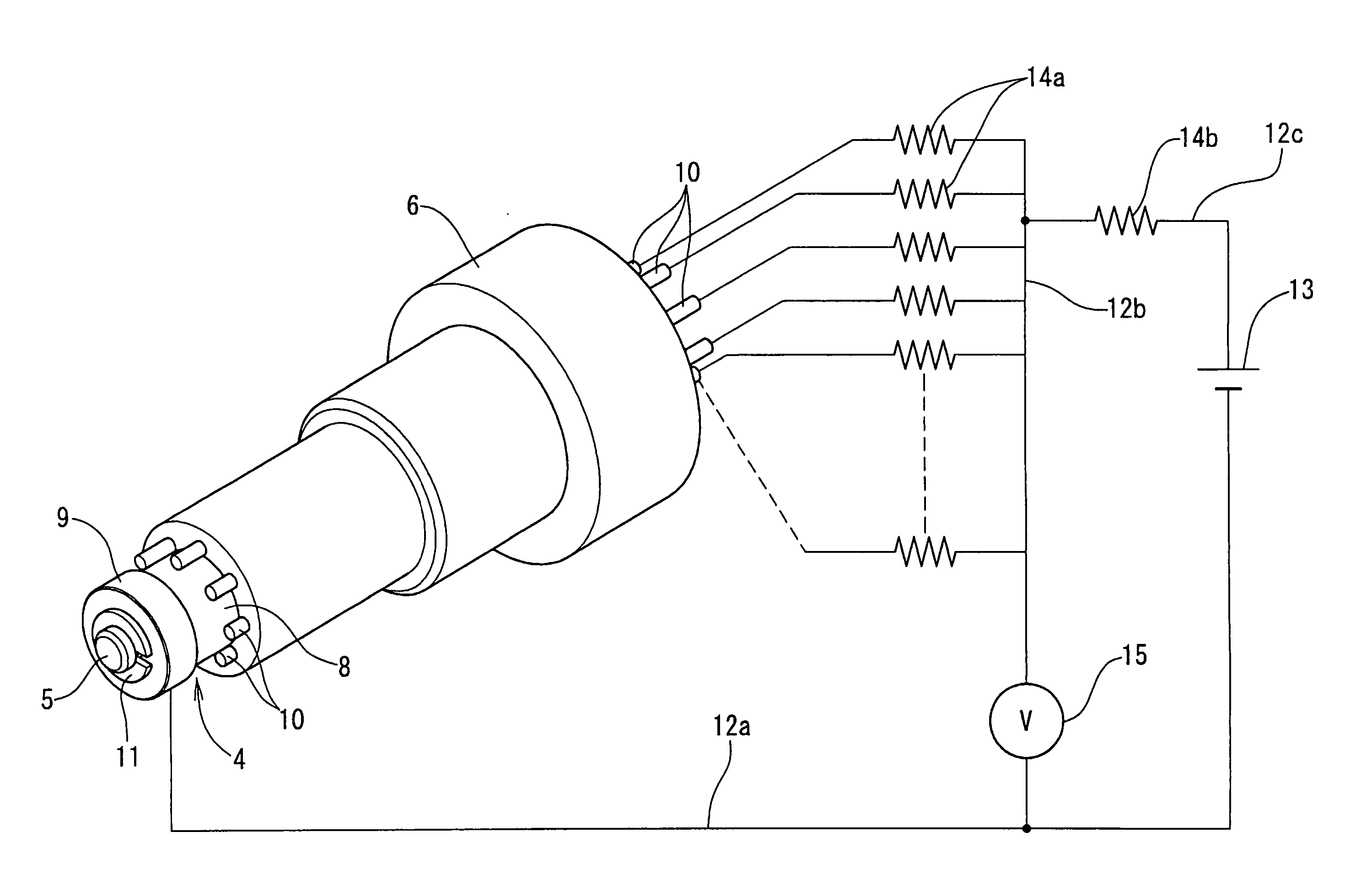
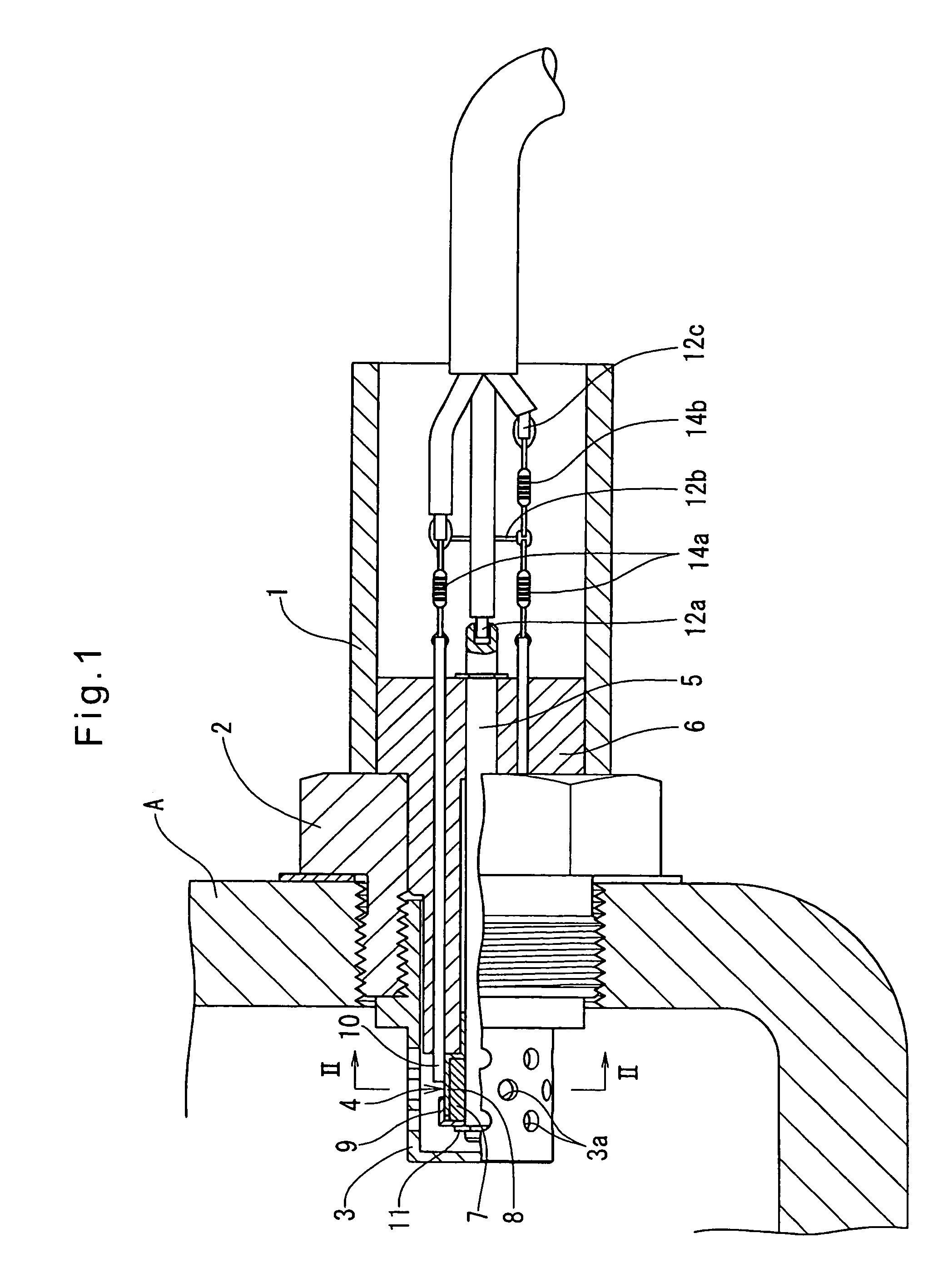
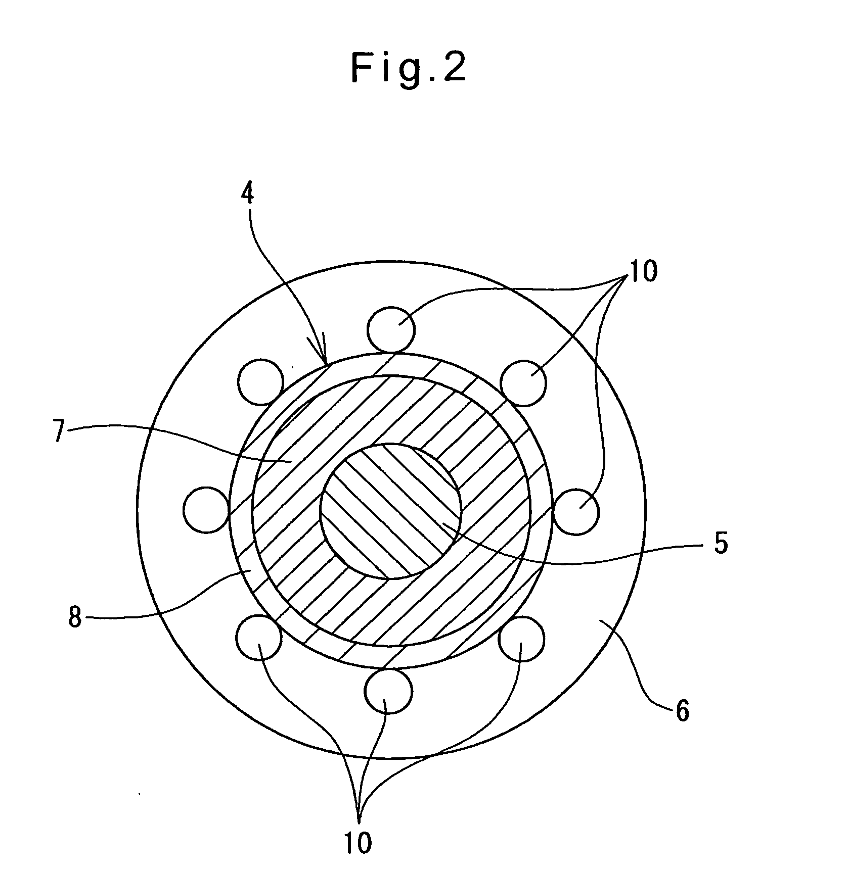
[0017] Now the embodiments of the invention are described with reference to the drawings. FIGS. 1-4 show the oil condition sensor of the first embodiment. It is used to determine the degree to which automotive transmission oil is contaminated with metallic powders, and includes, as shown in FIG. 1, a nut 2 threaded into a lower portion of a side wall of an oil pan A for transmission oil, a casing 1 fixed to the nut 2 outside the oil pan A, and a head cover 3 threaded into the nut 2 inside of the oil pan A so as to be immersed in the oil. A sensor head assembly 4 is mounted in the head cover 3. The head cover 3 is formed with a plurality of holes 3a through which oil in the oil pan A can flow into the head cover 3.

[0018] A rod 5 made of a conductive material extends through the casing 1 and is held in position so as to be coaxial with the casing 1 by a holder 6 received in the casing 1. A ring-shaped permanent magnet 7 is fitted around the tip of the rod 5 protruding from the holder...


PUM

PropertyMeasurementUnit
poweraaaaaaaaaa
distanceaaaaaaaaaa
resistanceaaaaaaaaaa

Abstract

An oil condition sensor is proposed which can accurately determine the degree to which oil is contaminated with metallic powders. It includes a permanent magnet and a sensor head provided around the permanent magnet. The sensor head includes a cup-shaped electrode and a plurality of rod-shaped conductors that are axially spaced from the cup-shaped electrode. The conductors are connected to a power supply through separate resistors. When the amount of metallic powders in the oil increases, a greater number of conductors are electrically connected to the cup-shaped electrode. Thus, by finding the number of conductors electrically connected to the cup-shaped electrode, it is possible to determine the degree to which the oil is contaminated with metallic powders. Since the resistors need not be immersed in the oil, their specific resistivities will scarcely change, so that the degree of contamination of the oil can be determined with high accuracy.

Description

BACKGROUND OF THE INVENTION [0001] The present invention relates to an oil condition sensor used to check the degree of contamination of automotive transmission oil or engine oil. [0002] Such an oil condition sensor is mounted in an oil container for automotive transmission oil or engine oil and is used to check how the oil is contaminated with iron powder or other metallic powder that are produced when automotive parts are abraded against each other. A typical such sensor is disclosed in JP patent publication 2002-286697 (see especially its FIGS. 1-4). It includes a rod adapted to be immersed in oil. The rod carries magnets at its tip. A pair of electrodes are provided around the magnets, axially spaced from and opposed to each other. The sensor produces a signal corresponding to the resistance in the oil between the electrodes, which in turn corresponds to the amount of metallic powder in the oil. [0003] At least one of the electrodes is a resistor. Any conductive material in the ...

Claims


Application Information

Patent Timeline
Patent Type & Authority Applications(United States)
IPC IPC(8): G01N27/04G01N27/00G01N33/28G01R27/08
CPCG01N33/2888
Inventor ITOMI, SHOJI
Owner NTN CORP
Why Eureka
Try Eureka