Memory device on optical scanner and apparatus and method for storing characterizing information on the memory device

a memory device and optical scanner technology, applied in the field of optical scanners, can solve the problems of printing artifacts, variation in spacing, and further complicated laser beam scan path deviation in color devices, and achieve the effect of facilitating replacement of optical scanners and improving processing capabilities

Active Publication Date: 2005-09-29
LEXMARK INT INC
View PDF47 Cites 44 Cited by
  • Summary
  • Abstract
  • Description
  • Claims
  • Application Information

AI Technical Summary

Benefits of technology

[0008] According to one embodiment of the present invention, an optical scanner includes a memory device for storing operational data. The stored data enables a host electrophotographic device to compensate for variances in laser beam scan path, laser beam linearity, laser beam intensity, and other operational characteristics, and also as provides enhanced processing capability. The present invention thus enables an image forming system for which the replacement of the optical scanner is facilitated in the field without the need for special image analysis tools normally found in a production environment.

Problems solved by technology

Should the scan path of a laser beam deviate from the ideal scan direction, print artifacts may result.
Laser beam scan path deviation is further complicated in color devices because excessive color to color mis-registration may cause color variation among other print artifacts.
However, manufacturing tolerances, imperfections of optical devices in the optical system, and the inherent configuration of the printhead may cause variations in the spacing between written Pels along a scan line, which is referred to herein as scan line nonlinearity.
Determining such fundamental laser characteristics typically requires meticulous factory calibration and relatively tight tolerances in the optical components of the printhead, resulting in an increased time and cost to manufacture the corresponding electrophotographic device.

Method used


Image

  • Memory device on optical scanner and apparatus and method for storing characterizing information on the memory device
  • Memory device on optical scanner and apparatus and method for storing characterizing information on the memory device
  • Memory device on optical scanner and apparatus and method for storing characterizing information on the memory device

Examples


Embodiment Construction

[0016] In the following detailed description of the preferred embodiments, reference is made to the accompanying drawings that form a part hereof, and in which is shown by way of illustration, and not by way of limitation, specific preferred embodiments in which the invention may be practiced. It is to be understood that other embodiments may be utilized and that changes may be made without departing from the spirit and scope of the present invention.

The Optical Scanner

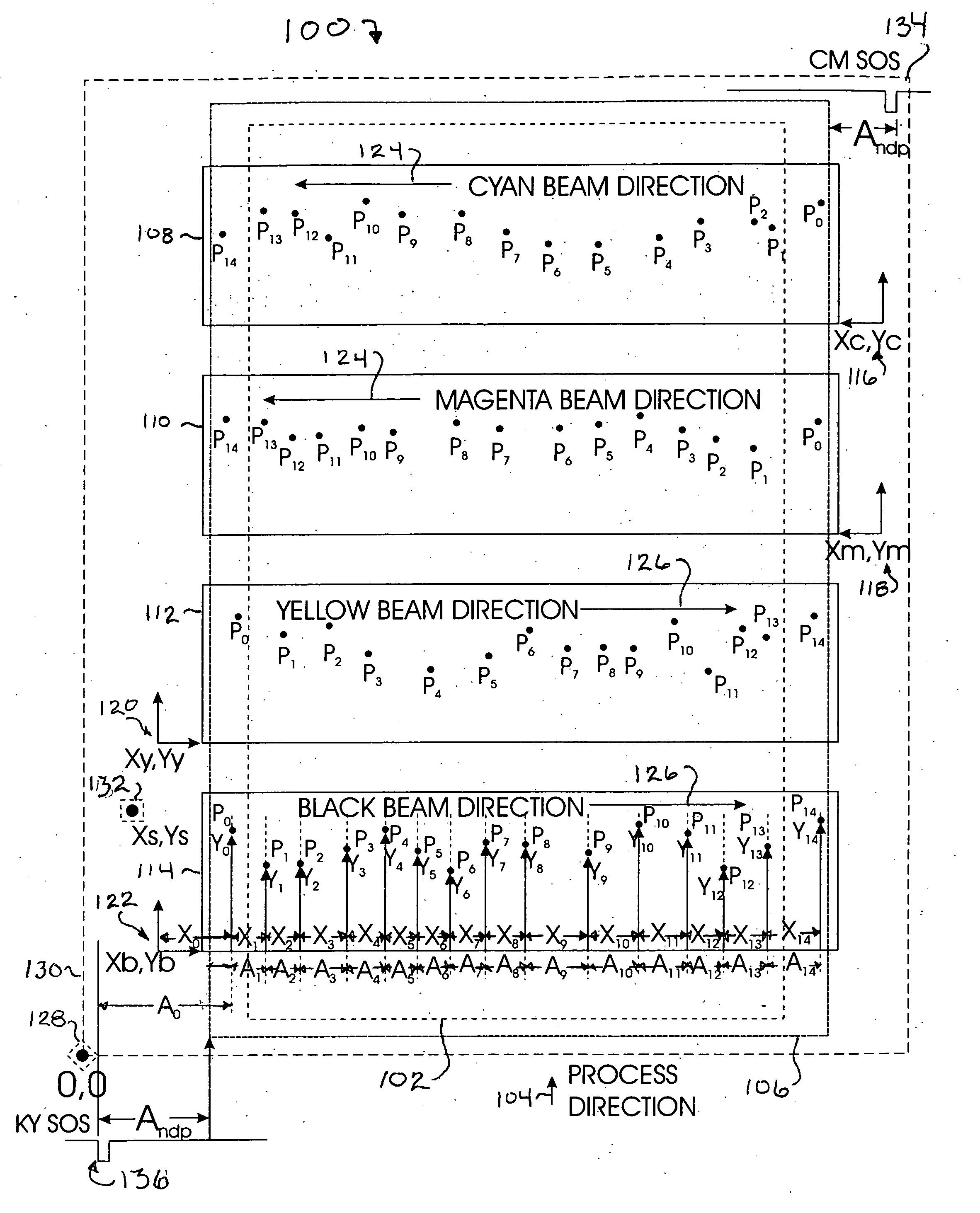
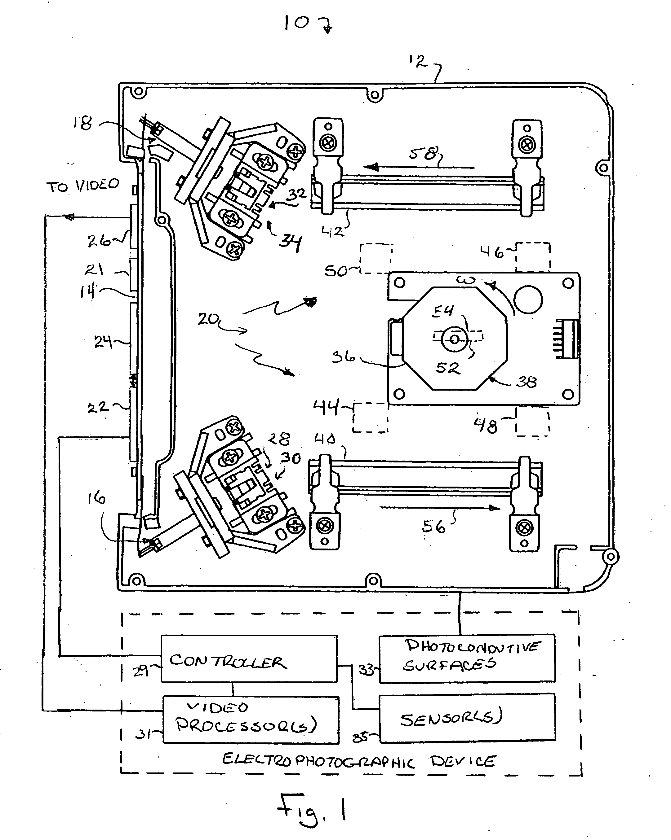
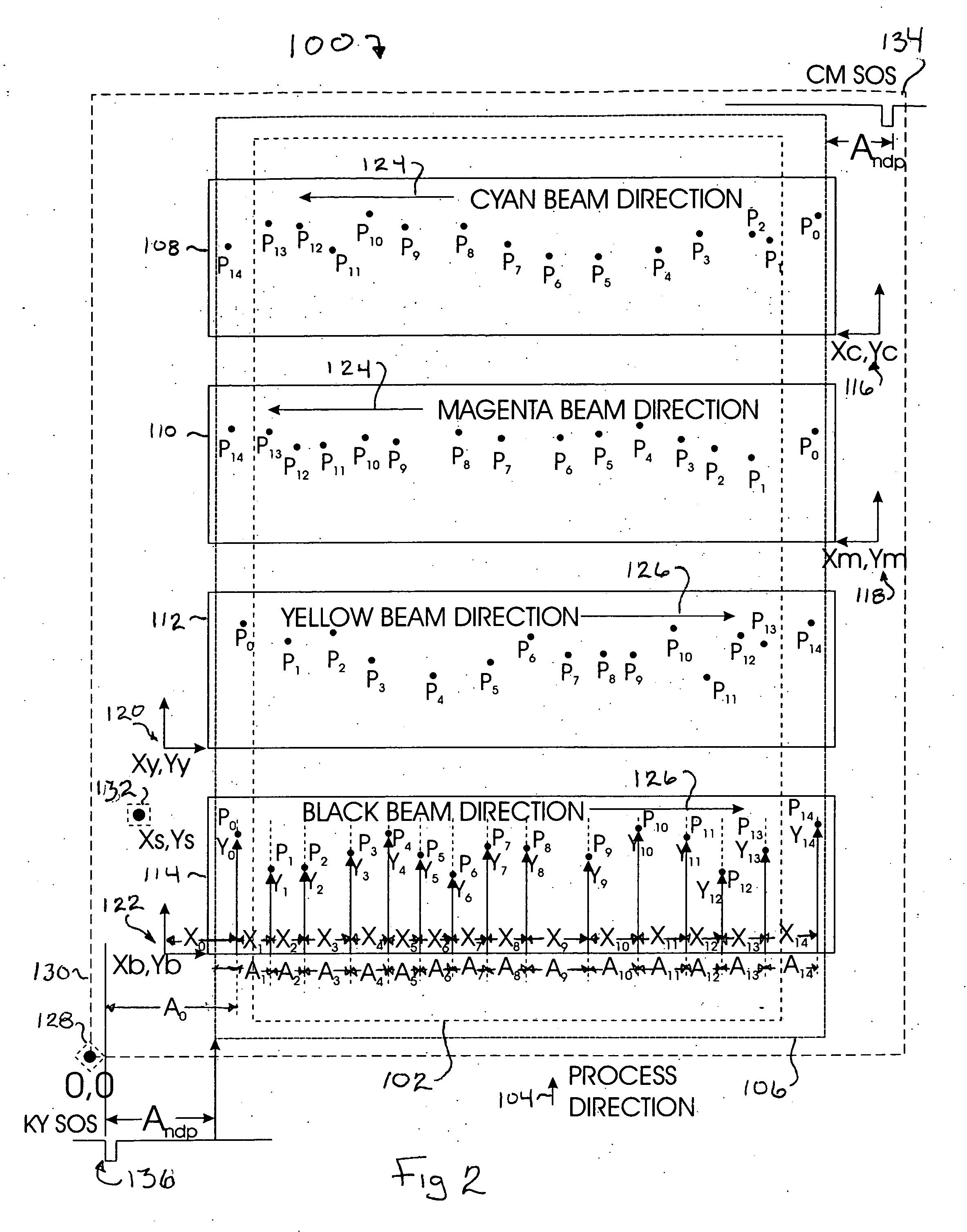
[0017] Referring to FIG. 1, an optical scanner 10, e.g., a printhead for a laser printer, includes generally, a housing 12, scanner circuitry 14, first and second laser assemblies 16, 18 and system optics 20. The scanner circuitry 14 provides electronics for driving lasers in each of the first and second laser assemblies 16, 18 including power management circuitry 21 for each laser. The scanner circuitry 14 further comprises a first interface 22 communicably coupled to a memory device 24, e.g., nonvolatile random ac...


PUM


Abstract

An optical scanner is provided having a memory device thereon. The memory device may store operational characteristics of the optical scanner or data that characterizes laser beam scan path and / or laser power requirements by each laser of the optical scanner. The memory device may be used to store historical information such as device temperature, cycles of operation and other historical information of components within a corresponding electrophotographic device. Still further, the electrophotographic device to which the optical scanner is installed may write operational data to the memory device, for example, to store a backup of registration and other operational parameters that are typically stored by the controller of the electrophotographic device.

Description

CROSS REFERENCE TO RELATED APPLICATIONS [0001] The present application is related to U.S. patent application Ser. No. ______, Attorney Docket 2003-0848, entitled “Systems For Performing Laser Beam Linearity Correction And Algorithms And Methods For Generating Linearity Correction Tables From Data Stored In An Optical Scanner”; U.S. patent application Ser. No. ______, Attorney Docket 2003-0844, entitled “Algorithms And Methods For Determining Laser Beam Process Direction Position Errors From Data Stored On A Printhead”; and U.S. patent application Ser. No. ______, Attorney Docket 2003-0839, entitled “Electronic Systems And Methods For Reducing Laser Beam Process Direction Position Errors”, each of which is filed currently herewith and hereby incorporated by reference herein.BACKGROUND OF THE INVENTION [0002] The present invention relates in general to an optical scanner such as a printhead, and in particular to an optical scanner including a memory device that stores operational char...

Claims


Application Information

Patent Timeline
Patent Type & Authority Applications(United States)
IPC IPC(8): B41J2/435B41J2/47H04N1/053H04N1/113H04N1/12H04N1/50
CPCH04N1/053H04N1/1135H04N1/12H04N1/506H04N2201/04793H04N2201/02443H04N2201/04798
Inventor COOK, WILLIAM P.FIELDS, THOMAS A.JOHNSON, ALLEN P.JONES, CHRISTOPHER D.REAM, GREGORY L.
Owner LEXMARK INT INC
Why Eureka
Try Eureka