Array device and mobile terminal

Active Publication Date: 2005-09-29
NEC CORP
View PDF2 Cites 45 Cited by
  • Summary
  • Abstract
  • Description
  • Claims
  • Application Information

AI Technical Summary

Benefits of technology

[0020] In the array device of the present invention, the first circuit receives input of an output signal of the plurality of sensors to generate a signal having such first directivity as passes a signal arriving from a direction of a target signal source, the second circuit receives input of an output signal of the plurality of sensors to generate a signal having such second directivity as cuts off a signal arriving from the direction of the target signal source and the third circuit emphasizes a signal arriving from the direction of the target signal source by correcting an output signal of the first circuit by using the output signal of the first circuit and an output signal of the second circuit. More specifically, because a signal having such sharp directivity as passes a signal arriving from the direction of the target signal source can not be directly generated only by the first circuit, a signal having such second directivity as cuts off a signal arriving from the direction of the target signal source (i.e. having a null in the direction of the target signal source) is separately generated by the second circuit to correct an output signal of the first circuit by an output signal of the second circuit. Here, according to the present invention, because the plurality of sensors are arranged such that a noise source fails to locate at a position of a null of the second directivity, the output signal of the second circuit has a signal arriving from the direction of the target signal source cut off, while having a signal arriving from the direction of the noise source passed. Accordingly, executing such correction processing as subtracting the output signal of the second circuit from the output signal of the first circuit by the third circuit enables generation of a signal with a signal arriving from the direction of the noise source satisfactorily suppressed and a signal arriving from the direction of the target signal source emphasized.

Problems solved by technology

When an error occurs in a target sound arriving direction, however, the target sound might be removed together with noise.
However, not only the number of microphones themselves but also the numbers of microphone amplifiers, interconnections and AD converters are increased to require more costs.
In addition, some of devices to which a microphone array is applied in practice such as a mobile phone inevitably limits the number of microphones that can be disposed due to constraints on space.
Under these circumstances, how a high performance microphone array is realized by as less number of microphones as possible is one of problems to be solved in putting an array device into practical use.
This is because when the number of microphone is small, in a case of the minimum number of two, in particular, spatial flexibility is too low to obtain sharp space separation capability, so that increasing sensitivity in a direction of a target sound source invites an increase in sensitivity in other directions than the target sound source direction, resulting in that satisfactory performance can not be ensured only by the improvement of a signal processing algorithm.
Nonetheless, there have been no conventional technique that intends to improve performance by microphone arrangement and structure taking limitations of signal processing algorithms into consideration and even an approach to improve performance from the side of microphone arrangement and structure is not found.

Method used


Image

  • Array device and mobile terminal
  • Array device and mobile terminal
  • Array device and mobile terminal

Examples


Embodiment Construction

[0059] Next, modes of implementation of the present invention will be described in detail with reference to the drawings.

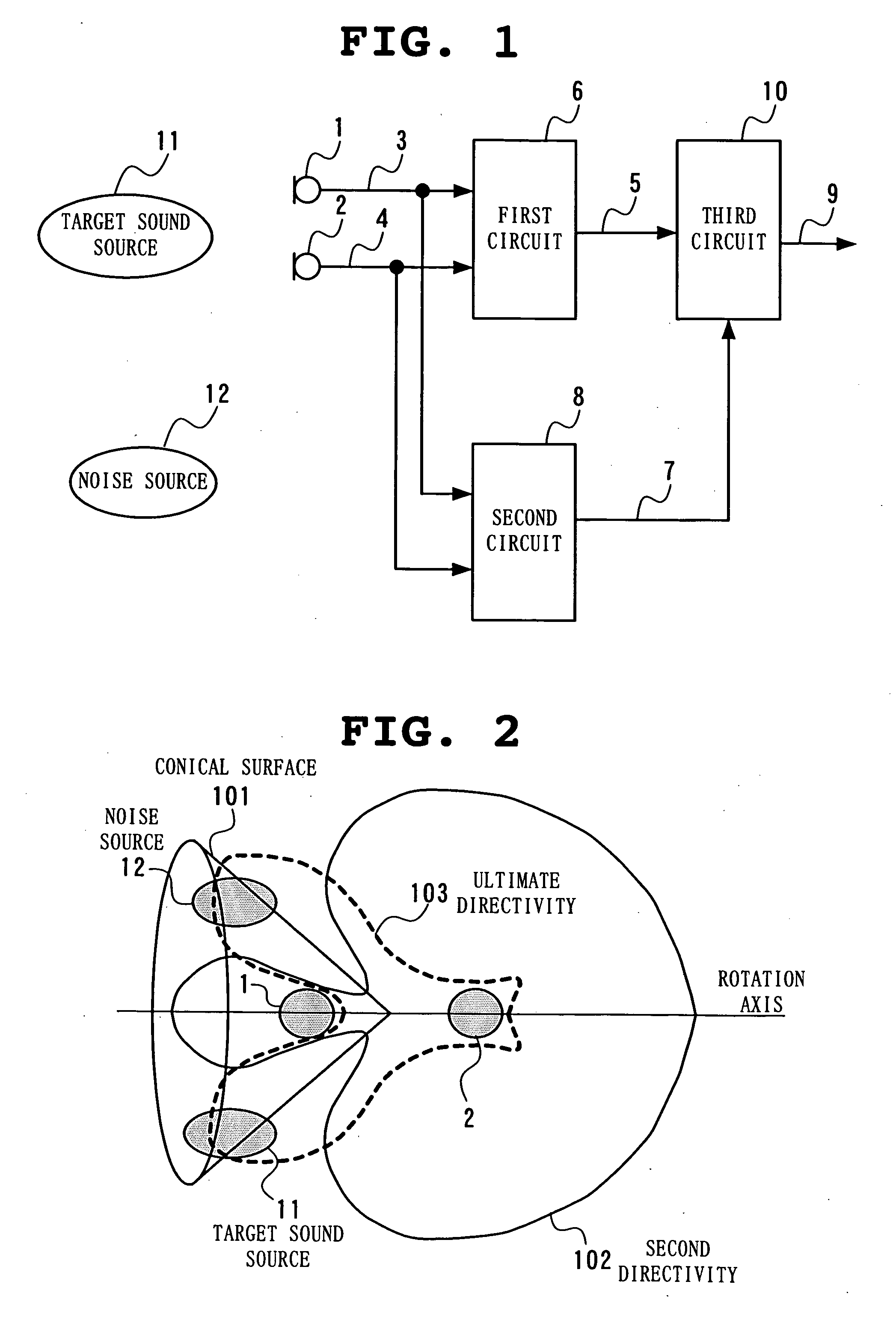
[0060] With reference to FIG. 1, one example of a microphone array to which the present invention is applied includes two microphones 1 and 2 which pick up a voice signal of a target sound source 11, a noise source 12, a first circuit 6 which receives input of output signals 3 and 4 of the microphones 1 and 2 to generate a signal 5 having such first directivity as passes a signal arriving from the direction of the target sound source 11, a second circuit 8 which receives input of the output signals 3 and 4 of the microphones 1 and 2 to generate a signal 7 having such second directivity as cuts off a signal arriving from the direction of the target sound source 11, and a third circuit 10 which receives input of the output signal 5 of the first circuit 6 and the output signal 7 of the second circuit 8 to correct the output signal 5 of the first circuit 6, thereby o...


PUM


Abstract

From output of a microphone, a first circuit generates a signal having first directivity which passes, and a second circuit generates a signal having second directivity which conversely cuts off, a signal arriving from a direction of a target sound source to output the obtained signals to a third circuit. Here, with two microphones disposed such that a noise source such as a speaker fails to locate at a position of a null of the second directivity, at the output of the second circuit, a signal arriving from the direction of the target sound source is cut off and a signal arriving from the direction of the noise source is passed. The third circuit corrects the output of the first circuit to output a signal with a signal arriving from the direction of the target sound source emphasized and a signal arriving from the direction of the noise source suppressed.

Description

FIELD OF THE INVENTION [0001] The present invention relates to an array device which space-selectively receives signals by using a plurality of sensors and, more particular, an optimum sensor arrangement technique. DESCRIPTION OF THE RELATED ART [0002] In general, an array device is used for receiving only a target signal out of a plurality of signal sources in the field of voice signal acquisition, sonar and radio communication. Used as a sensor are a microphone in a case of voice signal acquisition, an ultrasonic sensor in a case of a sonar and an antenna in a case of radio communication. In the following, description will be made, as an example, of a case of a microphone array using a microphone as a sensor. [0003] With a plurality of microphones disposed at different positions in space, a microphone array executes signal processing by using spatial information such as a phase difference derived from a difference in a propagation path to realize signal separation and noise remova...

Claims


Application Information

Patent Timeline
IPC IPC(8): G01S3/80H04M1/03H04M1/19H04M1/20H04R3/00
CPCH04M1/03H04M1/19H04M1/20Y10S367/901H04R3/005H04R2201/401H04R2499/11H04R1/406
Inventor HOSHUYAMA, OSAMU
Owner NEC CORP
Why Eureka
Try Eureka