Prismatic battery module and method for manufacturing the same

a battery module and battery technology, applied in the direction of cell components, flat cell grouping, sustainable manufacturing/processing, etc., can solve the problems of increasing the internal resistance, increasing the component resistance, and the entire connection path between the adjacent electrode plate group becoming longer, so as to reduce the internal resistance per cell

Active Publication Date: 2005-09-29
PANASONIC CORP +1
View PDF10 Cites 35 Cited by
  • Summary
  • Abstract
  • Description
  • Claims
  • Application Information

AI Technical Summary

Benefits of technology

[0012] In consideration of the above problems seen in the conventional technique, an object of the present invention is to provide a prismatic battery module in which the internal resistance per cell is reduced, and a method for manufacturing the same.
[0013] A prismatic battery module according to the invention includes a prismatic battery case having a plurality of prismatic cell cases connected to one another through separation walls, an electroconductive connector forming at least a part of the separation wall between the cell cases, an electrode plate group arranged in each cell case, and an electrolyte accommodated in each cell case. In the prismatic battery module, positive electrode plates and negative electrode plates, which together constitute the electrode plate group, are connected to respective electroconductive connectors arranged on both sides of the cell case. This construction requires fewer connection points and provides shorter electrical communication paths since the positive electrode plates of an electrode plate group in a cell case are connected to the negative electrode plates of an adjacent electrode plate group in an adjacent cell case only through the electroconductive connector, which forms the separation wall between the cell cases. As a result, internal resistance is reduced. Also, the prismatic battery module of the present invention does not require a collector plate and thus helps reduce its volume as well as its costs.

Problems solved by technology

A conventional rechargeable battery module made by connecting a plurality of cells together, each having an individual cell case, has a problem that the connection path between the cells is long and the number of connection points in the battery module is large, thereby increasing the component resistance leading to the increase of internal resistance thereof.
However, although the prismatic battery module 100 shown in FIGS. 32 and 33 is constructed so that the connection path from the positive and negative electrode plates to the respective collector plates 10a, 10b via the respective lead portions 9a, 9b is short, as is denoted by arrows in FIG. 34, the adjacent collector plates 10a, 10b of the associated electrode plate groups are connected at one point of both ends of the connection projections 11 located at the upper portions of the adjacent collector plates by welding and therefore, there have been seen problems that the entire connection path between the adjacent electrode plate groups becomes longer and in addition, the internal resistance between the cells becomes higher since the electrical communication between the adjacent collector plates is performed at only one point.
Furthermore, there have also been seen problems that the collector plates 10a, 10b employed in the battery 100 increases the manufacturing cost of battery correspondingly, and further, it is necessary to arrange the collector plates 10a, 10b on both sides of the electrode plate group 8 and to form the upper portion of the collector plates 10a, 10b so as to project beyond the upper end of the electrode plate group 8, thereby forcing enlargement of the volume of the cell case 4.

Method used


Image

  • Prismatic battery module and method for manufacturing the same
  • Prismatic battery module and method for manufacturing the same
  • Prismatic battery module and method for manufacturing the same

Examples


first embodiment

[0051] A first embodiment of a prismatic battery module of the present invention will now be described with reference to FIGS. 1 through 5, in which elements identical to those of the prior art described with reference to FIGS. 32 and 33 are denoted by the same reference numerals. The following description is primarily directed to the differences from the prior art.

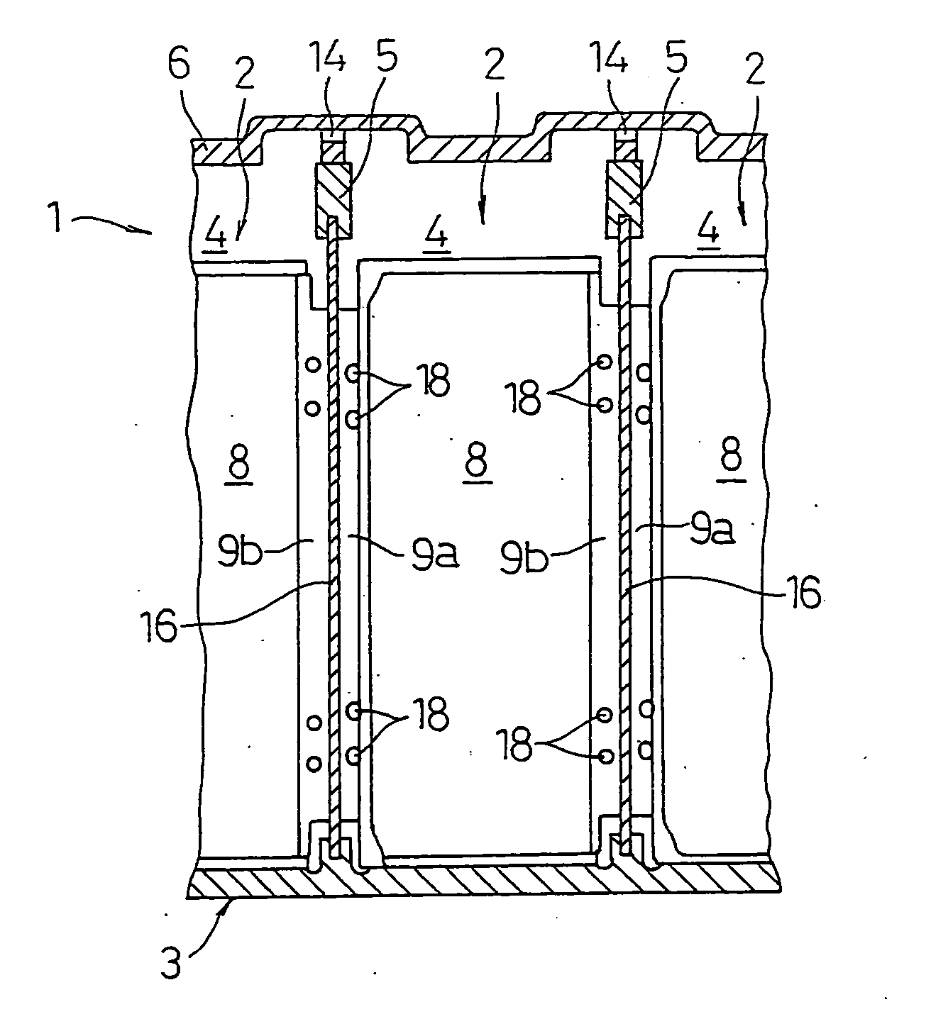
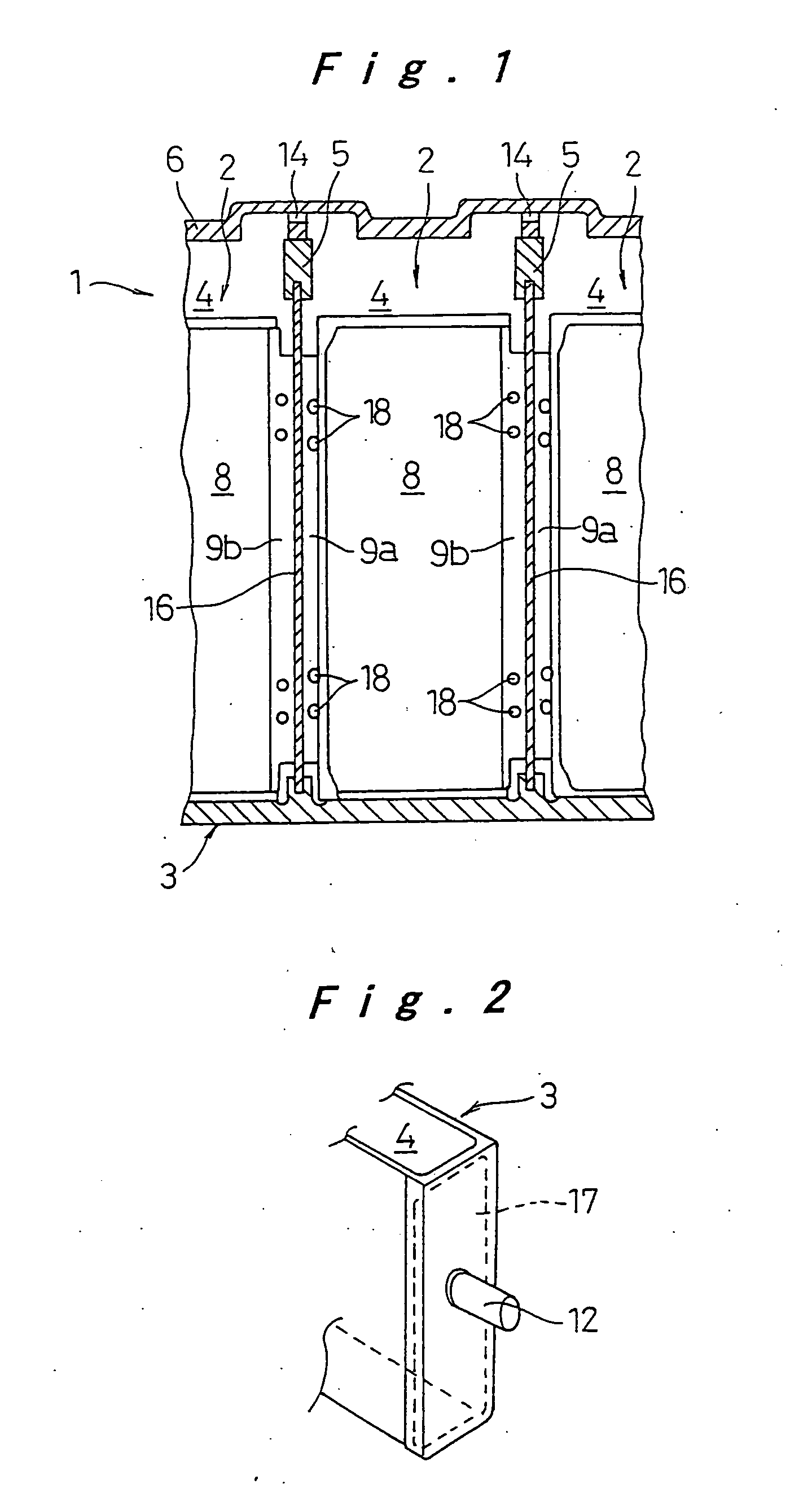
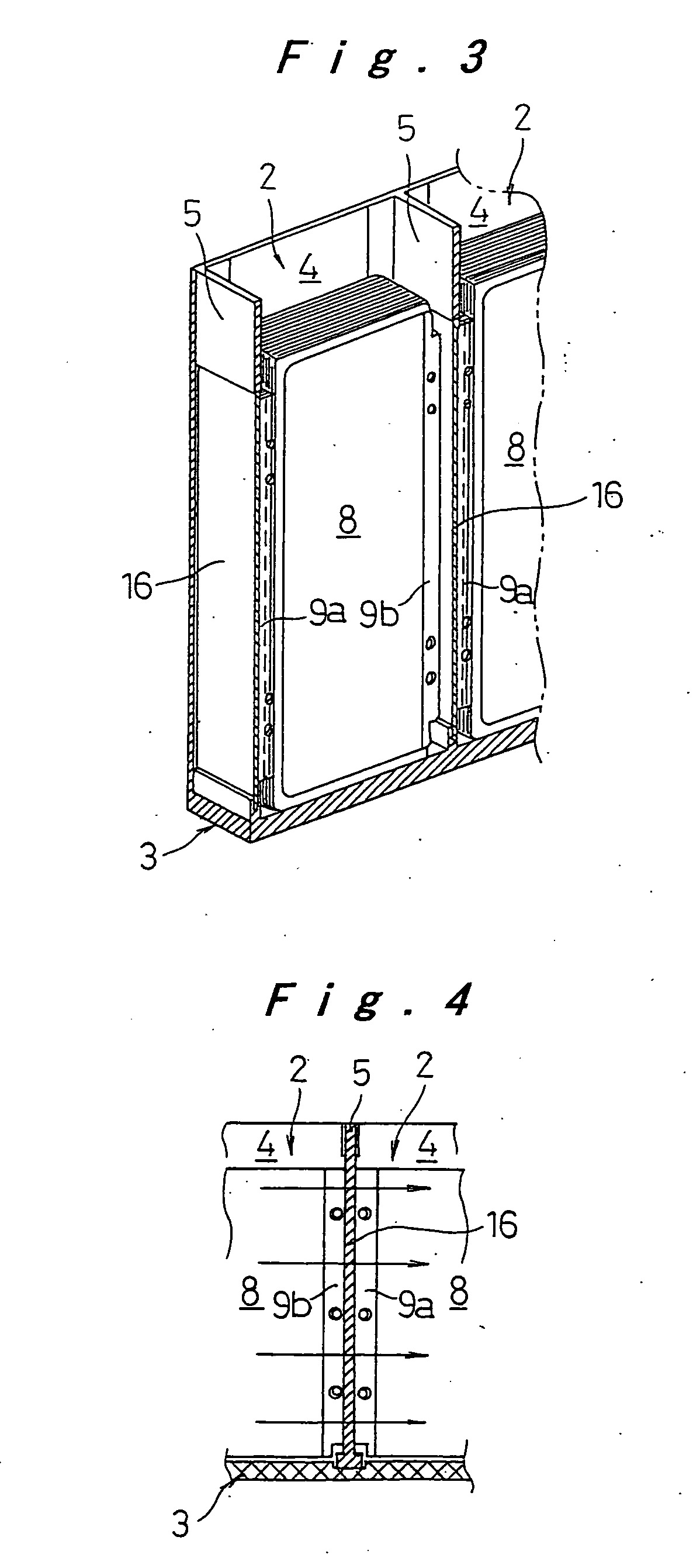
[0052] Referring first to FIGS. 1 to 3, a prismatic battery module 1 of the first embodiment includes a plurality of cells 2, each of which is constructed as a nickel metal hydride battery. A prismatic battery case 3, formed as a flat rectangular parallelepiped, includes a plurality of prismatic cell cases 4 for the cells 2. Each cell case 4 has short sides and long sides and is connected to adjacent ones by sharing the short sides, which serve as a separation wall 5 for forming the prismatic battery case 3. A lid 6 covers openings at the top of the cell cases 4 connected to one another. The lid 6 includes a communicatio...

second embodiment

[0059] Next, a second embodiment of the prismatic battery module of the invention is described with reference to FIGS. 6A and 6B. In the following description, elements identical to those described in reference to the previous embodiment are denoted by the same reference numerals and the description thereof will not be repeated. The embodiment, therefore, is described only in terms of the differences.

[0060] In this embodiment, a support pin 19 is placed through each of the support holes 18 formed in the lead portions 9a and 9b of the positive and the negative electrode plates of the electrode plate group 8. Also, vertical slots 20 are formed on the opposite side walls of the cell case 4 at positions opposite to one another on either side of the separation wall 5, which is arranged between the adjacent cell cases 4 of the prismatic battery case 3, so that the vertical slots 20 opposite to one another receive respective ends of the support pin 19 while ends of the lead portions 9a an...

third embodiment

[0063] Next, a third embodiment of the prismatic battery module of the invention is described with reference to FIGS. 7A and 7B.

[0064] In this embodiment, the planar connector plate 16 is welded to the lead portions 9a and 9b by applying a welding current that flows through a path between the adjacent support pins 19, which have been described in the second embodiment above and are arranged on both sides of the planar connector plate 16. The welding current flows through the support pin 19, the lead portions 9a, the planar connector plate 16, the lead portions 9b, and the support pin 19 adjacent to the first one to weld the contacts between the planar connector plate 16 and the lead portions 9a and 9b.

[0065] For this purpose, a pair of work openings 21 are preferably provided on the respective side walls of the prismatic battery case 3 for providing the welding current: one of the work openings 21 is formed on one of the opposite side walls at a position adjacent to one end of the...


PUM

PropertyMeasurementUnit
surface roughnessaaaaaaaaaa
distanceaaaaaaaaaa
electroconductiveaaaaaaaaaa

Abstract

A prismatic battery module includes a prismatic battery case having a plurality of prismatic cell cases connected to one another through separation walls, a planar electroconductive connector forming part of the separation wall between the cell cases, an electrode plate group arranged in each cell case, and an electrolyte placed in each cell case. Lead portions of positive electrode plates and negative electrode plates of the electrode plate group are directly connected to the electroconductive connector. The prismatic battery module requires fewer connection points and provides shorter electrical communication paths, thereby reducing internal resistance.

Description

CROSS REFERENCES TO RELATED APPLICATION [0001] This application is a continuation of prior U.S. application Ser. No. 09 / 996,908, filed Nov. 30, 2001, which is herein expressly incorporated by reference in its entirety.[0002] The present disclosure relates to subject matter contained in priority Japanese Patent Application Nos. 2000-364827 and 2001-243421, filed on Nov. 30, 2000 and Aug. 10, 2001 respectively, the contents of which is herein expressly incorporated by reference in its entirety. BACKGROUND OF THE INVENTION [0003] 1. Field of the Invention [0004] The present invention relates to a prismatic battery module and a method for manufacturing the same. More particularly, the invention relates to a prismatic battery module which is made by connecting a plurality of cells together and designed to reduce an internal resistance, and a method for manufacturing the same. [0005] 2. Description of Related Art [0006] A conventional rechargeable battery module made by connecting a plura...

Claims


Application Information

Patent Timeline
Patent Type & Authority Applications(United States)
IPC IPC(8): H01M10/04H01M10/34H01M50/528H01M50/103H01M50/529H01M50/534H01M50/536H01M50/54H01M50/541
CPCH01M2/0237H01M2/24Y10T29/4911H01M10/0413Y02E60/124H01M2/266Y02E60/10H01M50/529H01M50/54Y02P70/50H01M50/103H01M50/534H01M50/536
Inventor ASAHINA, TAKASHIHAMADA, SHINJIETO, TOYOHIKOFUKUDA, SHINSUKE
Owner PANASONIC CORP
Why Eureka
Try Eureka