Forward-Mounted Plunger Control for Retrofit Attachment to an Existing Syringe

a technology of forward-mounted plungers and syringes, which is applied in the field of syringes, can solve the problems of affecting the patient, small and thin-walled, and it is typically difficult to precisely cannulate with the needle tip, and achieves the effect of convenient attachment to an existing syring

Active Publication Date: 2005-09-29
PRECISION SCLERO LLC
View PDF11 Cites 35 Cited by
  • Summary
  • Abstract
  • Description
  • Claims
  • Application Information

AI Technical Summary

Benefits of technology

This patent describes a new device called an adaptor which can be attached to any standard syringe. It allows the user to hold and operate the syringe with one hand, making it easier to switch between aspirating and injecting substances. Overall, this makes medical procedures faster and more efficient.

Problems solved by technology

The technical problem addressed in this patent is the need for a low-cost device that allows for one-handed control over a syringe during both aspiration and injection phases, while reducing the risk of unstable needle placement or accidental extrinsic injection. Existing solutions involve complicated mechanisms or difficulty in attaching to standard syringes, making them less efficient and user-friendly.

Method used


Image

  • Forward-Mounted Plunger Control for Retrofit Attachment to an Existing Syringe
  • Forward-Mounted Plunger Control for Retrofit Attachment to an Existing Syringe
  • Forward-Mounted Plunger Control for Retrofit Attachment to an Existing Syringe

Examples


first embodiment

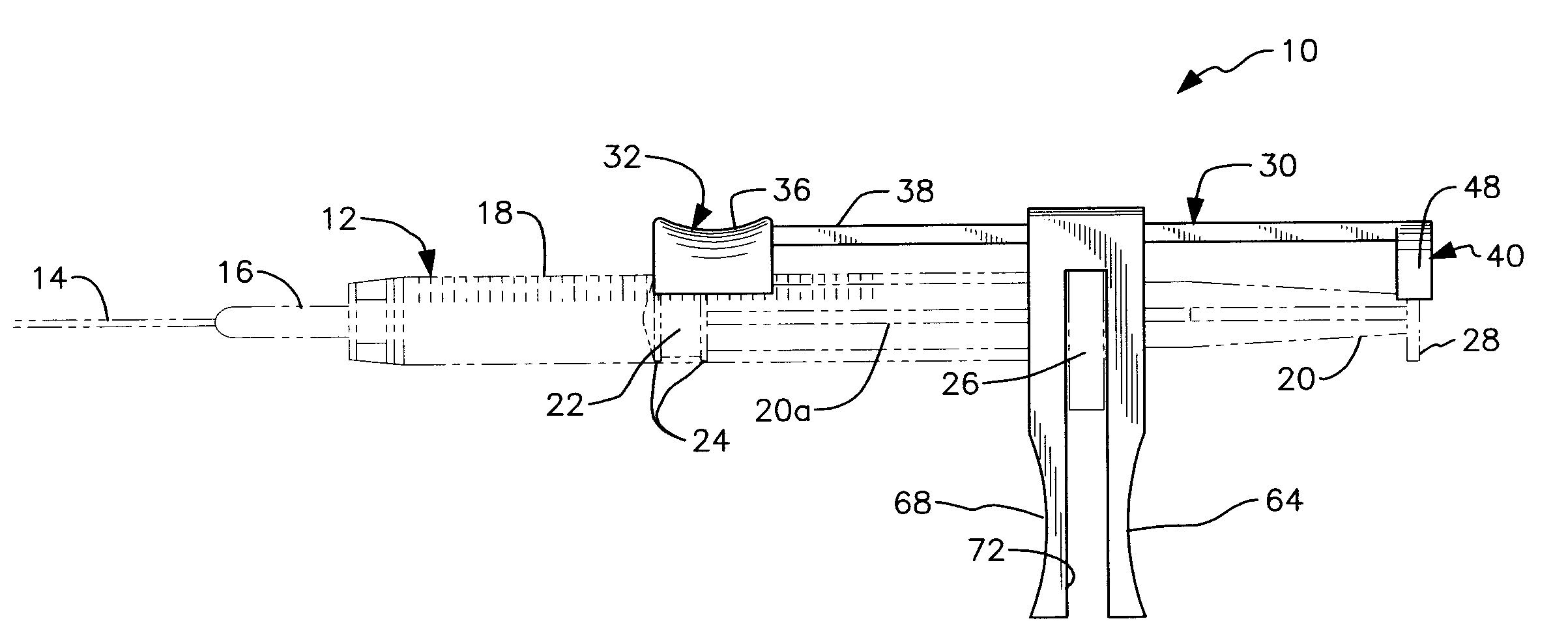
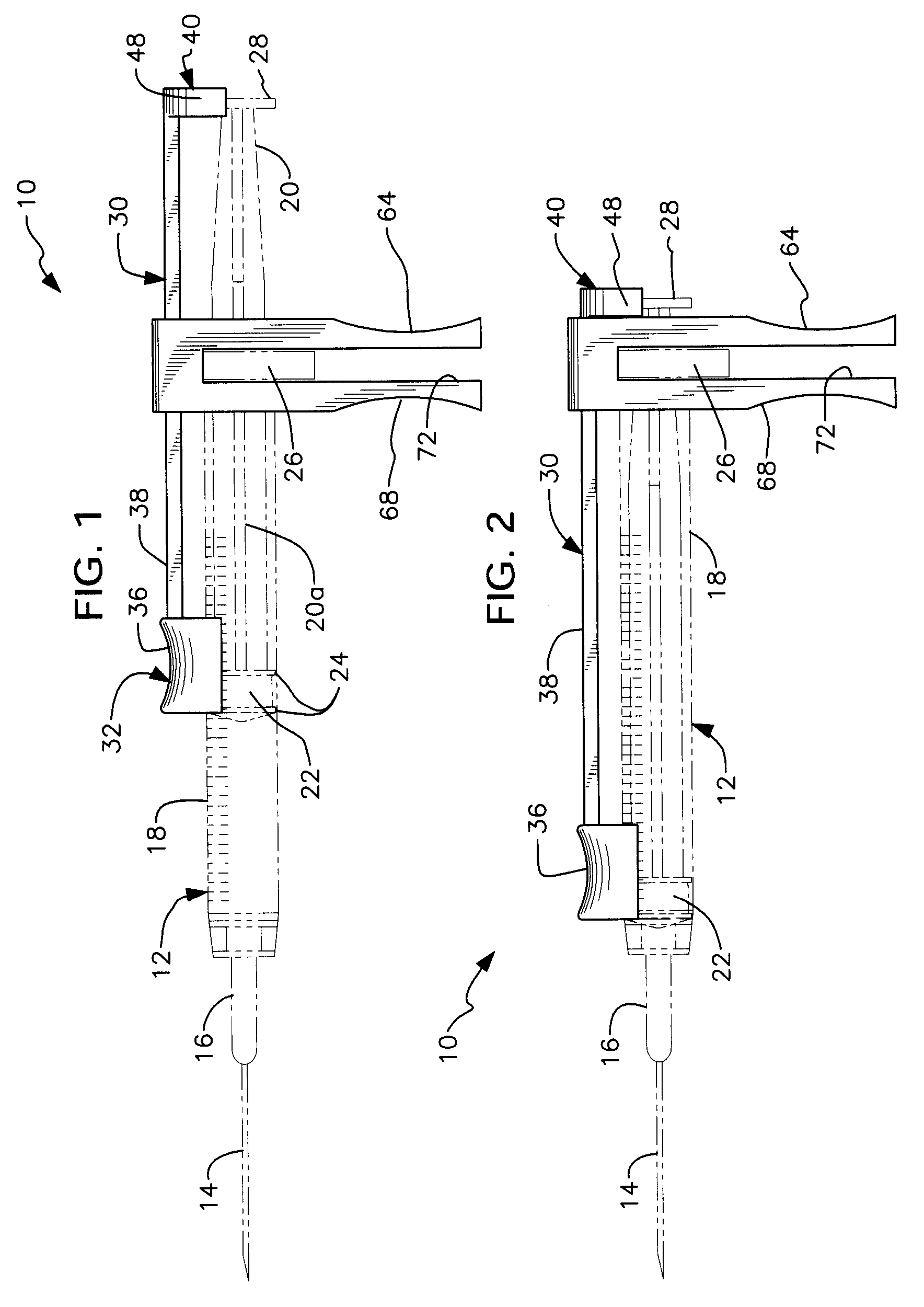
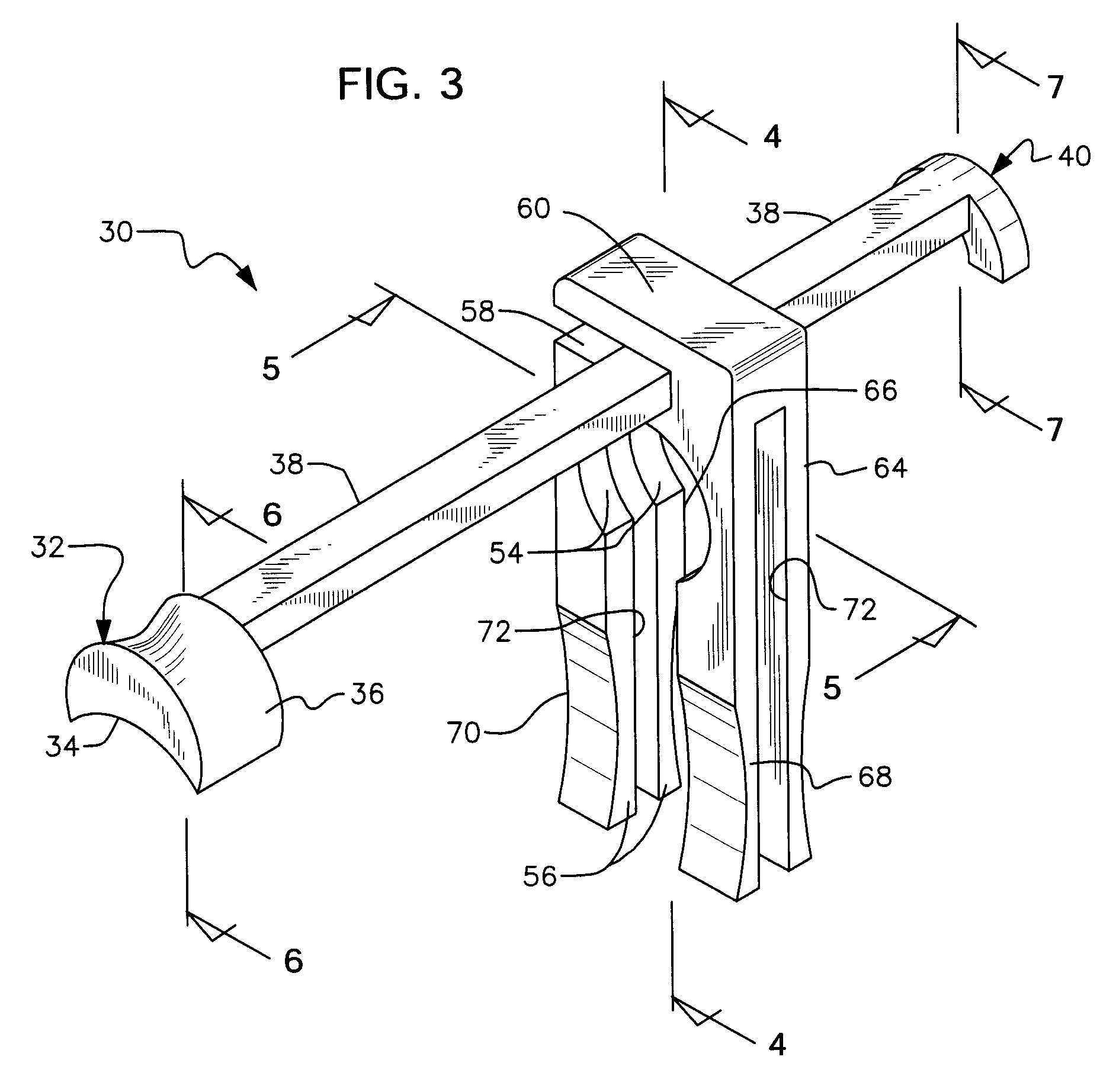
[0046] Plunger flange 28 is formed integrally with plunger 20 at the trailing end thereof as aforesaid. In a first embodiment, it is releasably engaged by flange housing 40 formed integrally with the trailing end of elongate connector 30. As perhaps best understood in connection with FIG. 7, flange housing 40 includes a top wall 42, leading wall 44, trailing wall 46, side walls 48 (see FIGS. 1 and 2), and an open bottom, thereby creating a cavity 50 (FIG. 7) for receiving and capturing plunger flange 28.

[0047] Elongate connector 38 is maintained in spaced apart, substantially parallel relation to barrel 12 by guide 52. As best understood in connection with FIGS. 3-5, guide 52 includes a barrel 18-receiving opening 54 and a vertically extending slot 56 that slideably receives barrel 18 when guide 52 is snap fit thereonto. The diameter of barrel-receiving opening 54 is greater than the breadth of slot 56 so that barrel 18 is retained within said opening 54. Adaptor 30 is made of a fle...

second embodiment

[0053] In a second embodiment, depicted in FIGS. 8A and 8B, flange housing 40 is replaced by flange-engaging housing 41 having a top half 41a and a bottom half 41b hingedly connected thereto by hinge 43 Said flange-engaging housing 41 is depicted in its open configuration in FIG. 8A, it being understood that said housing 41 must be open to receive flange 28. Said flange-engaging housing 41 is depicted in its closed configuration in FIG. 8B, it being understood that flange 28 would be captured therewithin in sandwiched relation between the top and bottom halves of said flange-engaging housing 41 when said housing is in its FIG. 8B configuration.

[0054] This second embodiment is used in the same way as the first embodiment, but flange-engaging housing 41 permanently engages flange 28, i.e., after top half 41a and 41b have been placed into their closed configuration, flange 28 is permanently housed therewithin because said half parts cannot be re-opened unless an extraordinary effort is...


PUM


Abstract

An adaptor for retrofit attachment to a syringe has a slide slideably mounted on the barrel of the syringe, a housing for releasably engaging a flange formed on the trailing end of the syringe plunger, an elongate connector for interconnecting the slide and the plunger housing, and a guide that releasably engages a flange formed at the trailing end of the barrel. Movement of the slide effects simultaneous and corresponding movement of the plunger. This allows a syringe operator to perform aspiration and injection in sequence with one-handed operation of the syringe. The slide is adjacent the leading end of the plunger so that the operator can see the leading end of the plunger. The user's fingers support the syringe from below. The flange housing permanently engages the flange in a second embodiment. In a third embodiment, the elongate connector and plunger are formed integrally at their respective trailing ends.

Description


Claims


Application Information

Patent Timeline
Owner PRECISION SCLERO LLC
Why Eureka
Try Eureka