
Disk repair structures for positioning disk repair material

a technology for positioning disks and repair structures, which is applied in the field of prosthetic vertebral disk repair implants and methods, can solve the problems of leg pain, and loss of muscle control, and causing injury or disease to the spinal disk, and reducing the height of the nucleus

Inactive Publication Date: 2005-09-29
KYPHON
View PDF10 Cites 302 Cited by
  • Summary
  • Abstract
  • Description
  • Claims
  • Application Information

AI Technical Summary

Problems solved by technology

Trauma or disease may displace or damage the spinal disk.
The herniated or so-called “slipped” nucleus can compress a spinal nerve, causing leg pain, loss of muscle control, or even paralysis.
Also, as the disk degenerates, the nucleus loses its water binding ability and deflates, which decreases the height of the nucleus.
In regions of buckling, either circumferential or radial anulus tears may occur, potentially resulting in persistent and disabling back pain.
Degenerated, diseased, or traumatized disks prevent people from working and can severely impact the lives of patients and their families.

Method used


Image

  • Disk repair structures for positioning disk repair material
  • Disk repair structures for positioning disk repair material
  • Disk repair structures for positioning disk repair material

Examples


embodiment

of FIG. 1

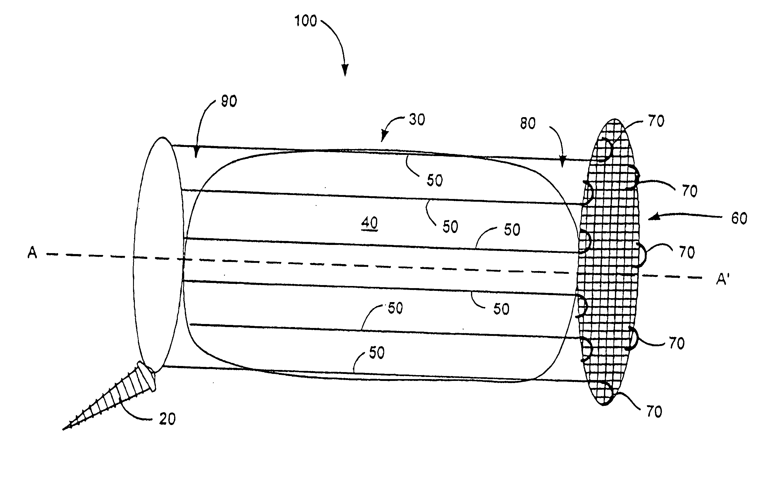
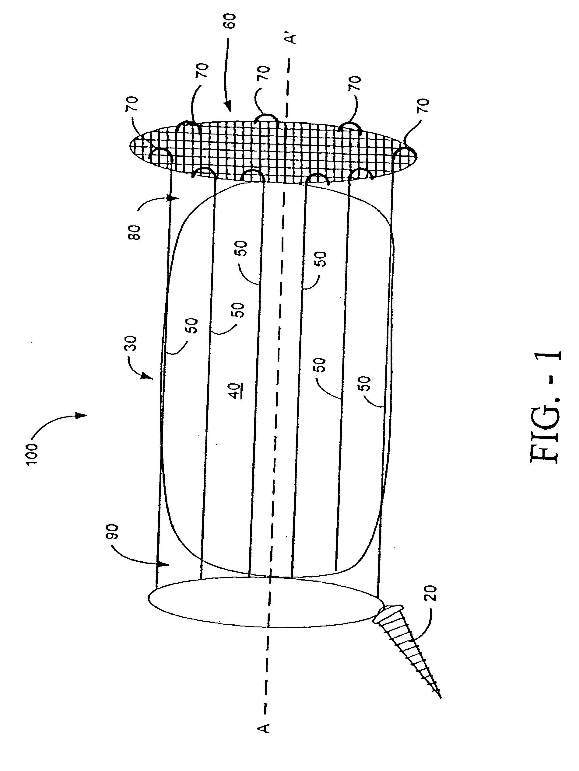
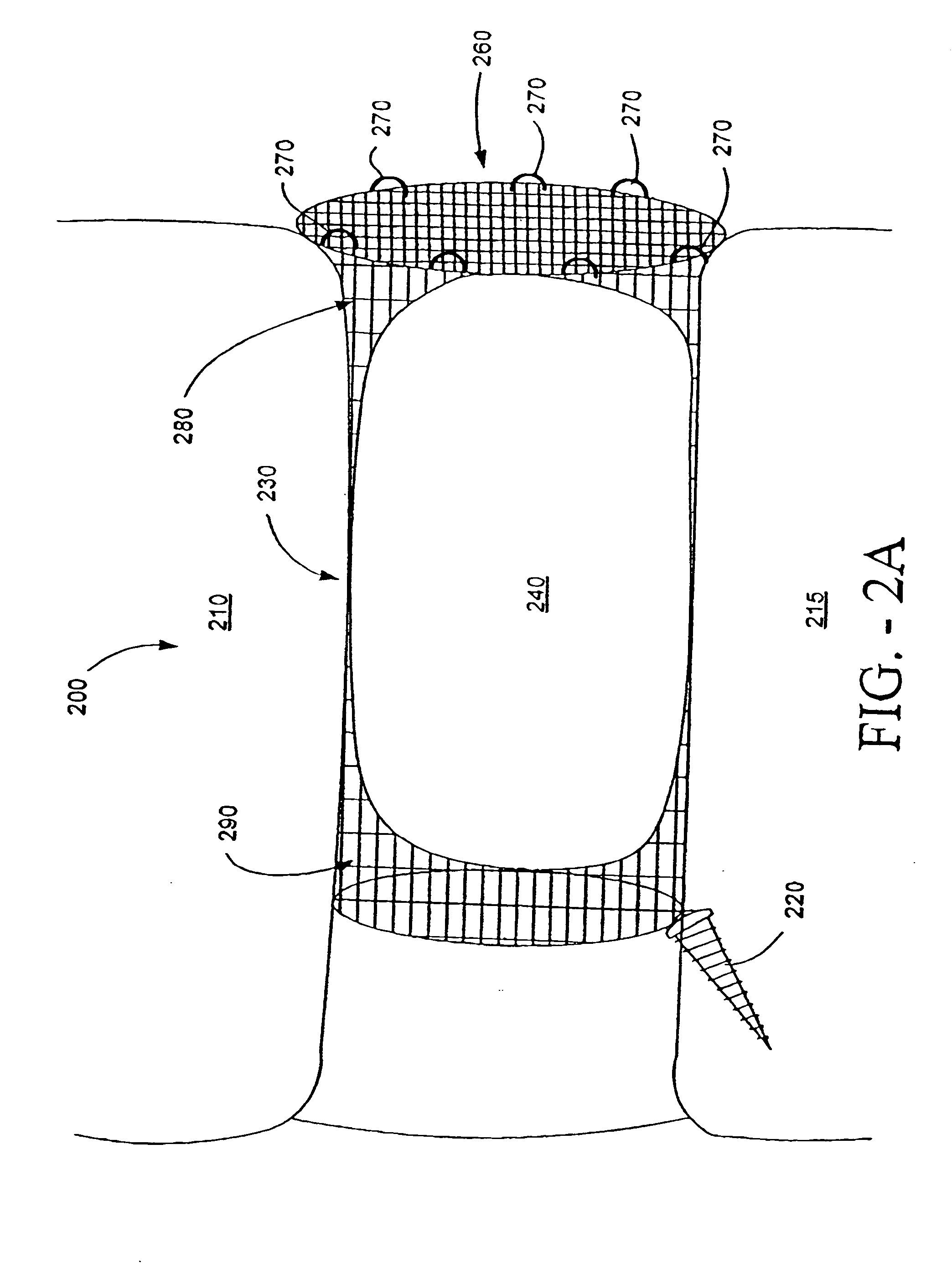
[0037] One preferred embodiment 100 of a prosthetic intervertebral spinal implant for repairing an intervertebral disk is shown in FIG. 1. In this embodiment, the implant 100 comprises a flexible wire structure 30 that is substantially cylindrical and has an interior hollow space 90. The flexible wire structure 30 further has a longitudinal axis, labeled here as A-A′. The plurality of wires 50 comprising the flexible wire structure 30 can have various configurations. For example, in FIG. 1, the plurality of wires 50 runs substantially parallel to the longitudinal axis A-A′. Other configurations also within the scope of this disclosure are depicted in FIGS. 2A, 2B, AND 3. The plurality of wires 50 can be made of a flexible biocompatible metal such as nitinol, aluminum, titanium, or stainless steel.

[0038] The prosthetic intervertebral spinal implant 100 further comprises an anchoring means 20, connected with the flexible wire structure 30 at a first end of the longitudinal a...


PUM

PropertyMeasurementUnit
Structureaaaaaaaaaa
Flexibilityaaaaaaaaaa
Heightaaaaaaaaaa

Abstract

The present invention is directed to a device that can be placed between two adjacent vertebrae, and that is used to repair an injury or defect in the anulus of the intervertebral disk. The implant is characterized by having a flexible structure anchored to the vertebral bone, the flexible structure connected with a patch held in place over the injury or defect. The flexible structure has a hollow interior space which can sustain inside it a hydrogel cushion. The hydrogel cushion acts as a shock absorber for the spine, maintains height of the intervertebral disk space, and prevents further disk herniation due to the narrowing of the intervertebral disk space.

Description

PRIORITY CLAIM [0001] U.S. Provisional Patent Application No. 60 / 534,316 entitled DISK REPAIR STRUCTURES FOR POSITIONING DISK REPAIR MATERIAL, James F. Zucherman et al, filed Jan. 5, 2004 (Attorney Docket No. KLYCD-05005US1).CROSS-REFERENCE TO RELATED APPLICATIONS [0002] The present application is related to the following United States Patent Application No. XX / XXX,XXX filed on XX / XX / 2004, Attorney Docket No. KLYCD-05005US2, filed concurrently with the instant application, and incorporated fully by reference. FIELD OF THE INVENTION [0003] This invention relates to a prosthetic vertebral disk repair implant and method. BACKGROUND OF THE INVENTION [0004] The spinal column is a biomechanical structure composed primarily of ligaments, muscles, vertebrae and intervertebral disks. The biomechanical functions of the spine include: (1) support of the body, which involves the transfer of the weight and the bending movements of the head, trunk and arms to the pelvis and legs; (2) complex phys...

Claims


Application Information

Patent Timeline
IPC IPC(8): A61F2/00A61F2/02A61F2/30A61F2/44A61F2/46
CPCA61F2/441A61F2310/00047A61F2/4611A61F2002/30062A61F2002/30075A61F2002/30092A61F2002/30224A61F2002/30235A61F2002/30289A61F2002/30462A61F2002/30677A61F2002/3085A61F2002/4435A61F2002/444A61F2002/4495A61F2002/4622A61F2210/0004A61F2210/0014A61F2210/0061A61F2220/0075A61F2230/0069A61F2230/0091A61F2310/00011A61F2/442
Inventor ZUCHERMAN, JAMES F.HSU, KEN Y.
Owner KYPHON
Learn More