Patient lift and transfer device and method

a technology for transferring devices and patients, applied in medical science, nursing beds, ambulance services, etc., can solve problems such as patient discomfort, and achieve the effect of high comfort and security of patients and minimal patient manipulation

Inactive Publication Date: 2005-10-06
AARESTAD JEROME K
View PDF47 Cites 57 Cited by
  • Summary
  • Abstract
  • Description
  • Claims
  • Application Information

AI Technical Summary

Benefits of technology

[0013] In accordance with the present subject matter, a lift and transfer device is provided in which a single operator can transfer a patient from one location to another location with minimal patient manipulation while providing a high level of comfort and security to the patient. The device in one form includes a wheeled base which may be wheeled in a transverse direction under, for example, a bed to be positioned at a first location. A lift is supported at a side of the base to be transversely adjacent to the bed when substantially the remainder of the base is under the bed. A patient support assembly supported on the lift has first and second transversely extending support arms cantilevered from a longitudinally extending main support arm pivotally supported on the lift. The first support arm carries a back support section which supports a back and other parts of the body. The second support arm carries a leg support section which supports a patient under and behind the knees. The patient is supported while leaving the lower torso, buttocks and thighs substantially free.

Problems solved by technology

The support provides for comfortable placement of the patient's arms and is arranged to bear weight but not enough to cause discomfort to a patient.

Method used


Image

  • Patient lift and transfer device and method
  • Patient lift and transfer device and method
  • Patient lift and transfer device and method

Examples


Embodiment Construction

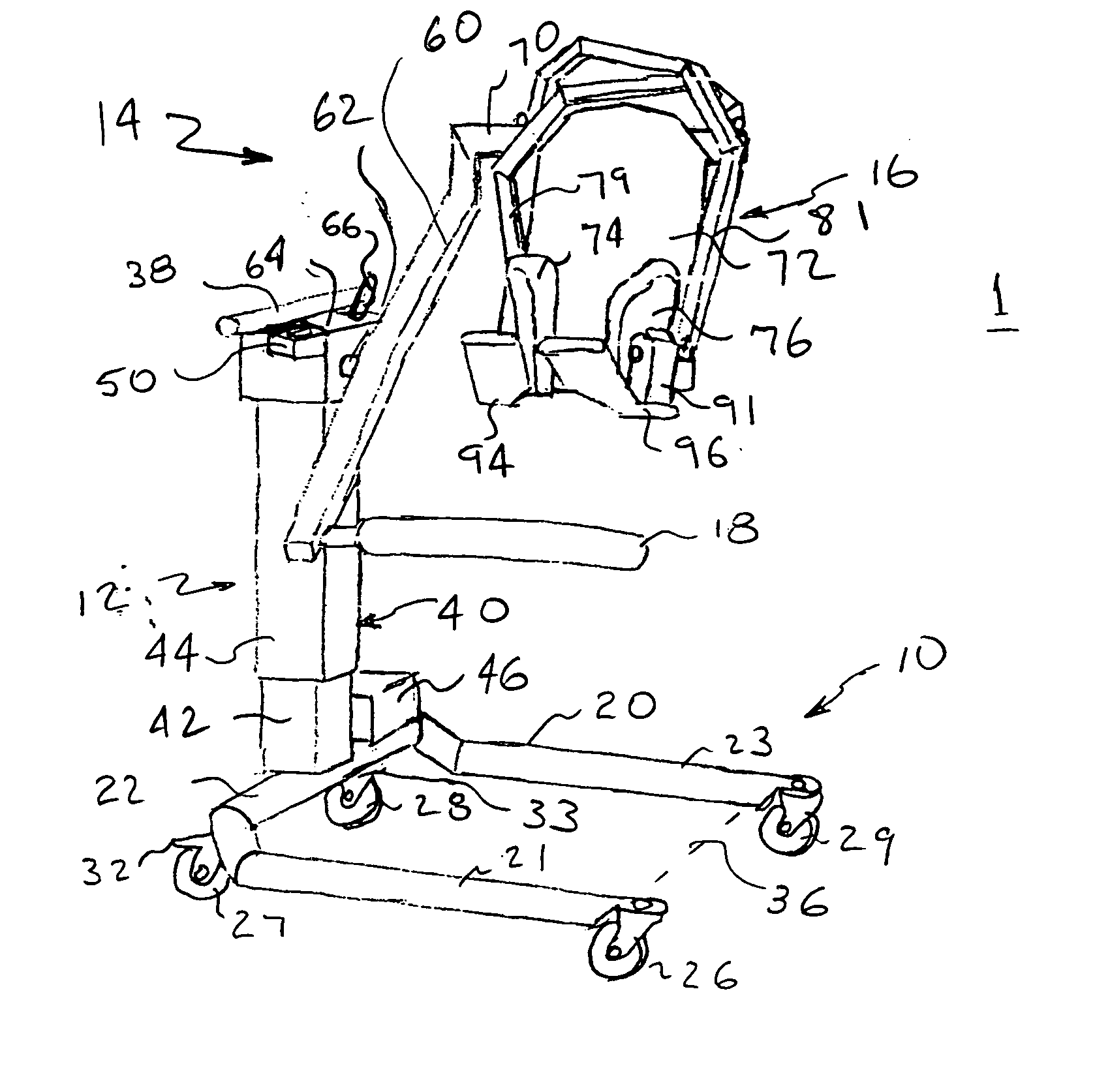
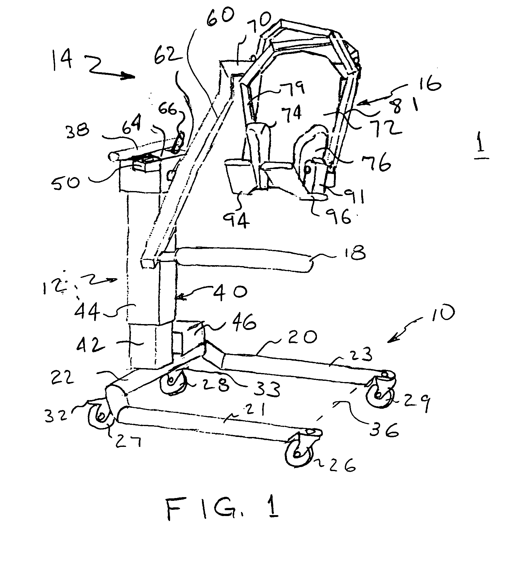
[0034]FIG. 1 is an axonometric illustration of a patient lift and transfer device 1 constructed in accordance with the present subject matter. The device 1 transfers a patient 2 (FIG. 5) from a first location to a second location as further illustrated below with respect to FIGS. 8-11. The patient 2 may be in a first position, e.g., resting on a bed, at the first location and shifted to a second position, e.g., sitting, for transfer to the second location. The resting position could be the supine position. Alternatively, the patient 2 could have a back tilted upwardly and the knees could be raised. The lift and transfer device 1 includes a transport section 10 which achieves movement from the first location to the second location. The lift and transfer device 1 is moved by an operator to engage the patient 2 while the patient 2 is supported on a support device, e.g. a bed, a wheelchair, or a toilet. A lift section 12 raises and lowers the patient 2 onto or off of the support device....


PUM


Abstract

In a lift and transfer device and method, a patient support assembly supported on a lift on a wheeled platform includes a main support arm pivoted to the lift. First and second transversely extending support arms respectively carrying a back support section and a leg support are cantilevered from the main support arm. The main support arm is positioned for lifting the patient from a bed. The main support arm is rotated from a first to a second angular position for lowering a patient to a wheelchair. First and second pivot arms each have an upper end pivotally supported to the back support section and a lower end having a torso grip pad positioned adjacent one side of the patient. Horizontal force applied by each torso grip pad and friction provide patient support. Further device forms are provided for bariatric patients and for use with other types of lifts.

Description

CROSS-REFERENCE TO RELATED APPLICATIONS [0001] This application claims priority to U.S. Provisional Patent Application Ser. No. 60 / 560,083 filed Apr. 6, 2004, the disclosure of which is incorporated herein by reference in its entirety.FIELD OF INVENTION [0002] The present invention subject matter relates to a device and method for lifting a patient in a first position in one location, transporting the patient to a second location, and depositing the patient at the second location in a desired position. BACKGROUND OF THE INVENTION [0003] A patient lift and transfer device is commonly known as a device that transports a patient who is in a first position at a first support. The patient may, for example, be in a supine position on a bed. The patient may be moved to a second support and positioned in a selected position which may be the same or different from the first position by such a patient lift and transfer device. For example, the patient may be moved to a wheelchair and deposite...

Claims


Application Information

Patent Timeline
Patent Type & Authority Applications(United States)
IPC IPC(8): A61G7/10
CPCA61G7/1015A61G7/1017A61G7/1019A61G7/1042A61G7/1044A61G7/1046A61G2200/52A61G7/1061A61G7/1084A61G2200/16A61G2200/32A61G2200/34A61G7/1053
Inventor AARESTAD, JEROME K.
Owner AARESTAD JEROME K
Why Eureka
Try Eureka